


front edge of the fuselage side, at each of these marks. At the
bottom line, measure back 1/2" from the front edge of the tape and
make a mark. On the top line, again measure back 1/2" and make
a mark. Use a straightedge to connect these two marks with short
vertical lines at each horizontal line.
These are the drilling
locations for the blind mounting nuts. Repeat this process on the
other side of the fuselage.
b) Without the mufflers installed on the engine, slide the cowl over
the engine pushing it back toward the fuselage. With our F.P.E. 6.8
twin, we found that in order to properly fit the cowl in place, we had
to first relieve the cowl at the choke location at the bottom of the
carburetor. We did this neatly, using a Dremel
®
Tool and a small
sanding bit (see Cowl Modification section).
With this small
clearance opening made, the cowl fit easily in place.
c) The engine prop support should now be centered in the cowl
opening in front view. To do this, we used a few pieces of scrap
balsa, cut to wedge shape. These were then placed between the
cowl and the engine prop support at the positions shown,
adjusting them as needed to center the engine to the cowl.
d) In side view, the cowl must now be positioned with clearance for
the spinner backplate - about 1/8" to 3/16" or so. Put the spinner
backplate on the engine and position the cowl with this clearance.
Once this position is established, use pieces of masking tape on
the top and bottom of the cowl to hold it in place to the fuselage.
Again using masking tape, place a piece of tape vertically on the
fuselage side with its forward edge aligned with the rear edge of
the cowl. Add a second piece of tape in the same position on the
opposite fuselage side. Remove the cowl.
e) Use a small triangle aligned with the forward edge of the
fuselage side, to transfer the forward hole location marks back to
the rear cowl edge pieces of tape. What you now have is the
locating information for the three required mounting holes for each
side of the fuselage. This information now needs to be transferred
to the exterior surface of the cowl for drilling purposes.
sparkplug wires to each cylinder head and in providing good wiring
proximity for the power and timing extension leads.
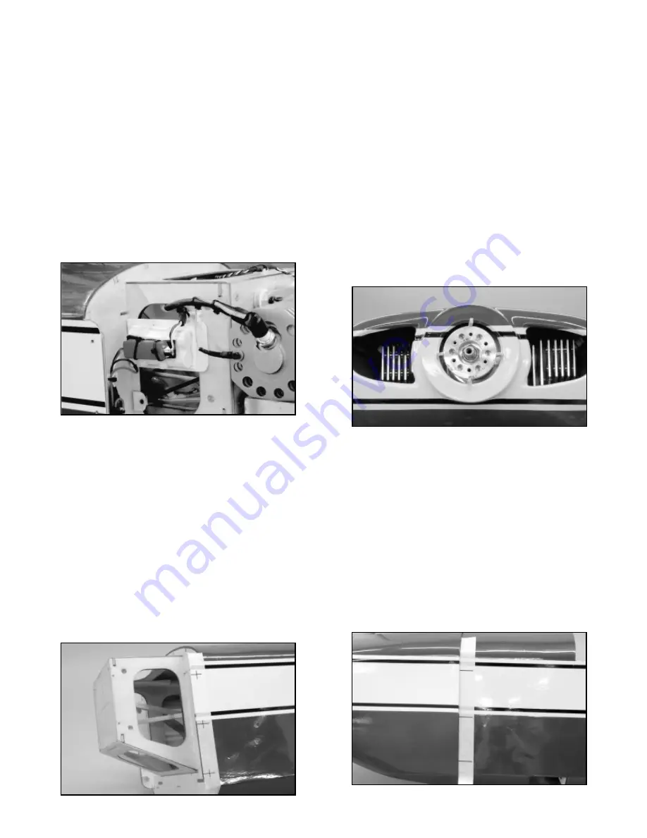
We mounted our 2400 mAh ignition battery pack (a 2-cell 7.4 volt
Li-Ion pack) and its 5.4 volt voltage regulator together, on a simple
tray made from 1/8" lite-ply. To keep the battery pack from shifting,
we cut and glued a perimeter of 1/4" balsa triangular stock to the
lite-ply base.
A 1/4" foam rubber pad was cut to fit into this
perimeter opening and the battery pack and voltage regulator were
mounted to the tray using two cable ties. The tray was then glued
to the outer side face of the right firewall support structure. This
mounting location provides easy wiring connector access to both
the ignition module and the ignition On/Off switch.
Last, to turn the ignition system on and off, as well as having the
ability to easily charge the ignition battery pack externally, we used
a Maxx Products "Soft Mount One-Piece Charge Switch", P/N
3470. We located this switch on the bottom right front side of the
fuselage, just behind the cowl.
Mounting The Cowl:
With the engine accurately mounted in place to the firewall, the
fiberglass cowl can now be positioned and mounted to the
fuselage. From the kit contents, locate the cowl and the small bag
containing the mounting hardware - 6 each M3 x 10mm PWA Bolts
and 6 each Blind Mounting Nuts. The forward fuselage sides, just
ahead of the secondary firewall, have been reinforced with large
triangular balsa stock. Note that the triangular stock has been
relieved in three locations - top, middle, and bottom - on each side.
These circular openings are the locations for the M3 Blind
Mounting Nuts - three on each fuselage side - used to receive the
M3 cowl mounting bolts.
a) Place a piece of masking tape vertically onto the side of the
fuselage with its forward edge aligned with the front edge of the
fuselage side.
In front view, use a marker pen to mark the
approximate centers of each blind nut cutout onto the front edge of
the tape. Use a small triangle to strike a line 90
O
back from the
14