SIG EDGE 540T Assembly Manual Download Page 15

13

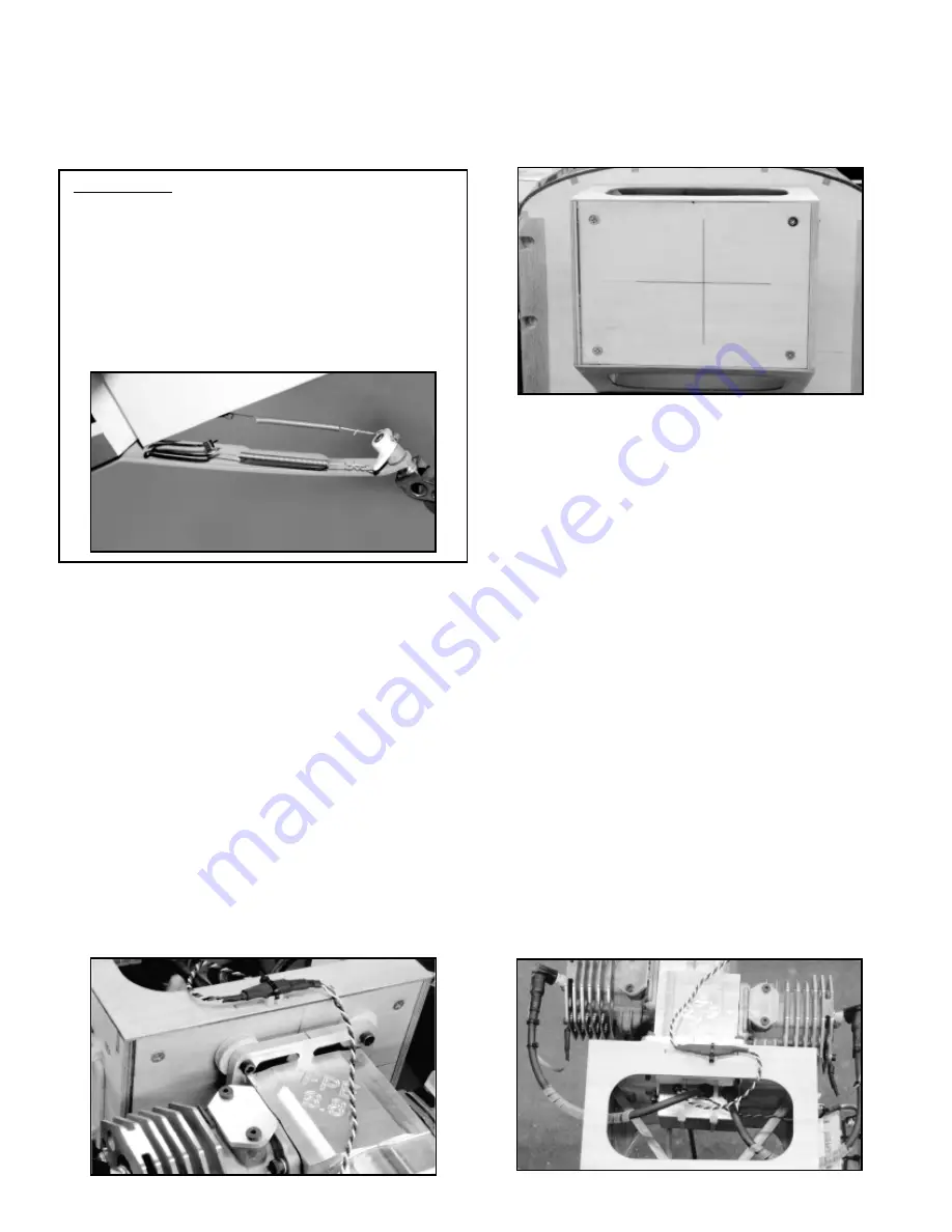
The firewall on the Edge 540T ARF has been factory-built with 2

O

of right thrust. The firewall has also been accurately marked with
vertical and horizontal centerlines.

These two lines, at their 

intersection, represent the centered position of the engine when it
is mounted to the firewall, taking into account the built-in 2

O

of right

thrust and the 7-7/32" distance to the cowl's spinner ring opening.

Using the vertical and horizontal centerlines, you can now 
accurately measure the motor mount plate location against the
firewall and its bolt hole mounting locations. If required, you must
also now make the firewall mounting spacers for your particular
engine, to move it forward enough to clear the cowl by 1/8" to 3/16"
when the spinner backplate is in place on the engine.

When the mounting bolt hole locations have been accurately
marked on the face of the firewall, use an electric drill and the
appropriate bit to make the required clearance holes for the bolts.
As also mentioned earlier, you will need to provide your own
mounting hardware. We used four #10-32 x 1-1/2" hardened steel
hex head bolts with #10-32 lock nuts and flat washers to mount our
F.P.E. 6.8 engine. The engine and spacers can now be mounted in
place to the firewall. Check the cowl fit by sliding it in place over
the engine (with the mufflers removed) and onto the front of the
fuselage. Make any adjustments necessary.

Mounting The Ignition Module:
We mounted the electronic ignition module for our F.P.E. 6.8
engine to a simple lite-ply tray that was made from scrap 1/8" lite-
ply, sized for our specific module. We glued a couple of pieces of
1/4" sq. balsa on each end of the tray to keep the module from
shifting and then glued two more pieces of 1/4" sq. balsa to the
opposite side of the tray to stand it off from the back face of the
firewall. We cut a piece of 1/4" foam rubber to fit between the tray
and the module. The module was then secured to the tray with a
pair of cable ties.

We used epoxy glue to then glue the module tray to the back face
of the firewall, directly behind the engine.

In our F.P.E. 6.8 

installation, this module mount location was perfect for routing the 

shown, center the bracket onto the bottom of the rudder, with the
left and right arms spaced equally on each side.

Mark the 

locations of the two mounting holes onto the rudder with a 
marking pen. Use a .042" dia. bit (#58 index drill) to drill two screw
guide holes at the marks just made. Mount the bracket in place
with the two T2 x 12mm PWA screws.

Mounting The  Engine:
As mentioned earlier in this manual, the distance between the 
firewall and the outside surface of the cowl, at the spinner location
is 7-7/32". As also mentioned, this distance is adjustable aft about
1/8" or can be moved forward as much as a 1/2" or so. Therefore,
you need to now measure the length of the engine that you plan to
install in your Edge. The measurement you need is the overall
length of the engine, from the back surface of the mounting plate
forward to the back surface of the spinner backplate when it's in
place.

This measurement will tell you how far forward your 

particular engine needs to be spaced from the firewall to fit within
the cowl, leaving about 1/8" - 3/16" clearance between the back
surface of the spinner backplate and the cowl itself.

For example, to mount our F.P.E. 6.8 twin cylinder engine in place
with the correct relationship to the firewall and the spinner 
backplate, we needed to space it's mount 1/4" forward from the 
firewall.

We did this by using 1/4" plywood to make four 1" 

diameter disks. These four disks were then center-drilled with a
.193" dia. bit (#10 index drill) to provide clearance holes for the four
#10-32 mounting bolts. The photo shows the firewall, spacers, and
the bolts already in place.

MODELER’S TIPThe connection between the two centering springs
and the "T" bracket on the bottom of the rudder can be made using
two small cable ties. Doing this allows easy and accurate centering
of the tail wheel to the rudder and also avoids metal-to-metal contact
between the spring ends and the "T" bracket. The only requirement
needed to do this is to drill oversize holes in the "T" bracket arms to
allow clearance for the cable ties. We used a 7/64" drill bit to drill out
these two holes in the bracket.

The centering springs are each

attached to the tail wheel tiller arms as usual. The opposite ends of
each spring were bent with round-nose pliers to create a couple of
small loops in the wire. The connection between the springs and "T"
bracket arms were then made with 4" cable ties at each spring.

Summary of Contents for EDGE 540T

Page 1: ...A S S E M B L Y M A N U A L KIT NO SIGRC100ARF ...

Page 2: ...ls 6 Mounting The Stabilizer Halves 6 Hinging Flight Surfaces 7 Hinge Gap Sealing 8 Aileron Servo Installation 8 Elevator Servo Installation 10 Landing Gear Wheel Pant Assembly 11 Mounting The Tail Wheel 12 Mounting The Engine 13 Mounting The Ignition Module 13 Mounting The Cowl 14 Fitting The Cowl 15 Fuel Tank Assembly 15 Fuel Tank Installation 16 Throttle Servo Installation 16 Rudder Servo Pull ...

Page 3: ...are To mount our F P E 6 8 Twin engine we used 4 each 10 32 x 1 1 2 Hex Head Hardened Steel Bolts 4 each 10 32 Lock Nuts 4 each 10 32 Flat Washers 1 INTRODUCTION Congratulations on the purchase of your SIG Edge 540T ARF kit This aircraft has been carefully designed tested and refined to offer you incredible performance coupled with outstanding airframe strength In terms of control response the Edg...

Page 4: ...rying to save money DO NOT try to save money on your choice of servos As also mentioned we chose to run our airborne system at 6 volts A 6 volt system provides considerably faster and more precise servo response This is very desirable especially when flying this airplane in 3D maneuvers Earlier we provided you with our recommended minimum torque requirements for the flight surface servos used in t...

Page 5: ...overed with SIG AeroKote covering film This high quality polyester covering film has been expertly applied using a beautiful and unique trim scheme designed specifically to provide maximum contrast between the top and bottom of the model This feature offers excellent attitude reference during 3D or IMAC maneuvers The SIG Edge 540T ARF model was manufactured and covered in a part of the world that ...

Page 6: ...lts 4 each M4 Washers 4 each T2 6 x 16mm PWA Screws Stabilizer Mounting Screws 1 Bag 8 each Heavy Duty Control Horns w Nylon Inserts 4 Left 4 Right 32 each T2 6 x 16mm Phillip Head Screws Control Horn Mounting Screws 2 each 08mm x 1200mm 47 Nylon Coated Steel Cables 4 each Steel Clevises with 2mm Threaded Rigging Couplers and Lock Nuts Rudder Pull Pull Connectors 4 each Copper Rigging Swages 3 5mm...

Page 7: ...venient to apply the graphics to the wing panels fuselage and rudder of the Edge 540T model before the assembly process However you can use the following instructions to apply your graphics either now or after you have completed the assembly steps Your Edge 540T ARF kit includes a beautiful and very large graphics sheet These graphics are of high quality and include a unique light tack clear carri...

Page 8: ...be at a 30O angle or so Finally remount the two stab halves in place to the fuselage and check the fit It should now be fine Remove the stab halves and tubes from the fuselage 3 The mounting tubes must now be secured in place in the stab halves using four T2 6 x 16mm PWA screws On the bottom surface of each stab half you will see two small pre drilled holes These are hole locations for the stab tu...

Page 9: ...nge line You want to leave the minimum possible gap Use alcohol and paper towels to carefully remove any visible signs of glue at each hinge location 7 Insert the front and rear mounting tubes in place into the stab making sure they both bottom out against their stops Insert the pointed end of the music wire into one of the pre drilled holes on the bottom of the stab Press the music wire against t...

Page 10: ...rns 2 left and 2 right horns You will need a total of 16 control horn mounting screws Again check the hinge gap for the closest possible fit while maintaining full movement ability Allow the glue to cure for at least 6 hours Before the glue fully cures we suggest checking the fit and movement of the surface adjusting it as needed 5 When the glue has fully cured carefully check the movement of the ...

Page 11: ...e into the inboard servo bay opening in exactly the same way as described above As mentioned earlier we used 18 servo extensions 4 Using the same instructions above mount the remaining two aileron servos in the opposite wing panel 5 If you are using a single receiver you now need plug the two servo extensions from each wing panel into a Y harness one harness for each wing panel The Y harness conne...

Page 12: ...t the two control horns to the R C links on each pushrod b Place the control horn mounting pad onto the surface of the aileron Turn the threaded metal control rod to adjust the distance of the control horn from the leading edge bevel of the aileron The correct position for the control horn on the aileron is with its forward mounting pad edge up to the bevel edge of the aileron The upright arm of t...

Page 13: ...ves The pushrod clevis locking nuts and clevis safety springs do not need to be tightened or slipped into place until after the final control movements are established later in this manual Landing Gear Wheel Pant Assembly From the kit contents locate the Fiberglass Wheel Pants bag the Main Wheel bag also contains wheel and pant hardware bag and the Main Landing Gear bag In addition you will need t...

Page 14: ...ighten the three mounting screws securely d The flat metal T bracket is now mounted to the bottom forward surface of the rudder This bracket is used to connect the two centering springs with the tail wheel tiller arm and the rudder As 12 g The Landing Gear Hatch Cover is now installed over the mounted landing gear using two T3 x 16mm PWA screws Note that both the access and clearance holes are alr...

Page 15: ...racket onto the bottom of the rudder with the left and right arms spaced equally on each side Mark the locations of the two mounting holes onto the rudder with a marking pen Use a 042 dia bit 58 index drill to drill two screw guide holes at the marks just made Mount the bracket in place with the two T2 x 12mm PWA screws Mounting The Engine As mentioned earlier in this manual the distance between t...

Page 16: ...ach side of the fuselage This information now needs to be transferred to the exterior surface of the cowl for drilling purposes sparkplug wires to each cylinder head and in providing good wiring proximity for the power and timing extension leads We mounted our 2400 mAh ignition battery pack a 2 cell 7 4 volt Li Ion pack and its 5 4 volt voltage regulator together on a simple tray made from 1 8 lit...

Page 17: ...age use a ruler to now measure the distance between one of the rear marks just made forward to the cross hair mark on the forward piece of tape Note and save this measurement g Place the cowl on a flat work surface resting on its rear edge With a small triangle and a marker pen make three 90O lines on the cowl surface at the mark locations just made Use a ruler to measure forward from the rear edg...

Page 18: ...ng bender to make the appropriate 75O 80O bend in the aluminum tubing overflow line allowing it to reach the inside top of the tank body We suggest chamfering the top of this tubing to keep it from touching and possibly closing off on the inside of the tank Use a second piece of aluminum tubing straight through the rubber stopper for the carburetor and tank clunk line connections Attach the provid...

Page 19: ... tool to squeeze the copper swage tube tightly over the cable locking it 17 servos aft back with the receiver s rudder servo and the airborne radio system battery pack s There are two servo cut outs located on each side of the center mounted rudder servo tray in the fuselage Locating the throttle servo into one of these openings is ideal Since the fuel tank is already mounted and plumbed on the le...

Page 20: ...ions to completely center everything Receiver Battery Pack Installation The receiver s and battery pack s were mounted on the built in radio tray in the fuselage of our Edge 540T models We made simple mounting platforms for our battery packs using lite ply We did not mount these pack mounts until after we had conducted our Center of Gravity routine described later in this manual We mounted our On ...

Page 21: ...erfectly level not nose down not tail down level If it s obvious that the airplane is not level then the balance of the airplane at the desired 25 CG location must be adjusted to achieve a level fuselage There are a variety of things that can be done to do this We routed the receiver antenna out of the fuselage and up to the top of the fin This positioning takes the antenna out of parallel with th...

Page 22: ...ample we used a carbon fiber spinner from Pete Models on our Edge and this unit weighs only 2 9 ounces Spinners can make a big difference in CG adjustments If the shifting of airborne components is just not practical then adding weight to the furthest possible point at the rear of the fuselage may be necessary Like all modelers we hate adding weight to any model but it is sometimes unavoidable Ext...

Page 23: ...ings are well within the capability of this model For your first landing we would Flying The purpose of this section is to guide you through the first test flight of your Edge 540T ARF model using advice and procedures that we feel will lead to your success This section has nothing to do with aerobatics Aerobatics will be covered after the test flights are made and the airplane is trimmed However ...

Page 24: ...D LUCK AND GOOD FLYING suggest that the upwind final approach be made with just a bit more speed than you might first want This ensures that the airplane will continue to fly without stall concerns Make sure the airplane is headed into the wind on final approach and use rudder input as needed to maintain a straight heading along with aileron input to keep the wings level Allow the model to sink sm...

Page 25: ... AMA membership is not necessarily mandatory it is required by most R C flying clubs in the U S and provides you with important liability insurance in case your R C model should ever cause serious property damage or personal injury to someone else ACADEMY OF MODEL AERONAUTICS 5161 East Memorial Drive Muncie IN 47302 Telephone 765 287 1256 AMA WEB SITE www modelaircraft org CUSTOMER SERVICE SIG MAN...

Page 26: ...EXTRA 540T LOG BOOK Date of first flight Comments 24 ...

Page 27: ...EXTRA 540T LOG BOOK Date of first flight Comments 25 ...

Page 28: ...by modelers for modelers The perfect power plant for the SIG Edge 540T ARF CHECK OUT A COUPLE OF GREAT SIG PRODUCTS THAT WILL COMPLIMENT YOUR EDGE 540T ARF Designed for the special needs of the gasoline powered flyer the Gas Passer Flight Box features an extra large compartment to hold a 3 8 l gallon bottle can or DuBro s EZ Fill 3 8 l gallon container And it wouldn t be a SIG flight box without r...

Reviews: