10
INSTALLATION & OPERATION
1
§3 Installation & Operation
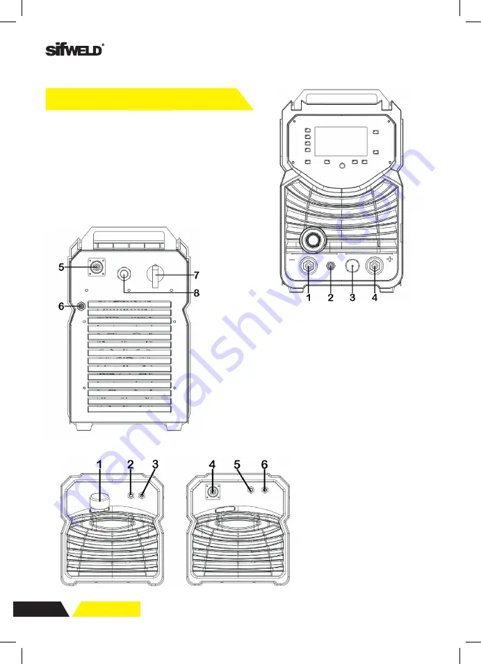
§3.1 Layout for Front and Rear panel
§3.1.1 Layout for welder
1 Negative output
: The welder’s negative polarity output.
2 Shield gas connector
: Is connected to the gas input pipe of torch.
3 Aero socket
: Is connected to torch switch control wire.
4 Positive output
: The welder’s positive polarity output.
5 Water box connector
: Is connected to the water box.
6 Shield gas input joint
: To connect one head of the gas hose while the other head is
connected to argon gas cylinder.
7 Power source switch
: Switch to “ON”, the welder is turned on, while switch to
“OFF”, the welder is turned off.
8 Power source input
: To connect power source.
1.4 Overview of Machine
Front View
Power Source Front Panel Layout
1. Negative output
2. Shield gas connector
3. Control socket
4. Positive output
Rear View
5. Water cooler connector
6. Shield gas input joint
7. Power source switch
8. Power source input
Water Cooler
1. Intake: From here, water or
coolant, antifreeze, etc. can be
injected into tank.
2. Water outlet for TIG (blue).
3. Backwater inlet for TIG (red).
4. The water cooling control
connector.
5. Water outlet for MIG (blue).
6. Backwater inlet for MIG (red).
INSTALLATION & OPERATION
1
§3 Installation & Operation
§3.1 Layout for Front and Rear panel
§3.1.1 Layout for welder
1 Negative output
: The welder’s negative polarity output.
2 Shield gas connector
: Is connected to the gas input pipe of torch.
3 Aero socket
: Is connected to torch switch control wire.
4 Positive output
: The welder’s positive polarity output.
5 Water box connector
: Is connected to the water box.
6 Shield gas input joint
: To connect one head of the gas hose while the other head is
connected to argon gas cylinder.
7 Power source switch
: Switch to “ON”, the welder is turned on, while switch to
“OFF”, the welder is turned off.
8 Power source input
: To connect power source.
INSTALLATION & OPERATION
1
§3.1.2 Layout for water cooling
1. Intake
: From here, water or coolant, antifreeze, etc. can be injected into tank.
2. Water outlet for TIG (blue).
3. Backwater inlet for TIG (red).
4. The water cooling control connector.
5. Water outlet for MIG (blue).
6. Backwater inlet for MIG (red).
Further Controls Explained
Outlet (2) and inlet (3) for TIG
The two nozzles on the same side of the intake (1) are used for TIG operation and can
be connected to the nozzles on TIG welding torch. Blue corresponds to the outlet: cold
water is delivered from the tank; red corresponds to the backwater inlet: hot water is
flowed into the tank for cooling.
Note
: Blue outlet and red backwater inlet must not be wrong!
Control connector (4)
Water tank control connector is used for inserting the connecting line. And connection
line is used to connect the water tank with wire feeder or water tank with welding
machine. It supplies power to the water tank through the connection line and receives
control and detection signals in time.


