AirLink LX40 Series Hardware User Guide
Rev. 2 January 2021
22
41112510
Wiring Diagrams
If you do not use the AC power adapter to power the LX40, you can wire the supplied DC
cable to your power supply. You have various options for wiring power to the LX40,
depending on your application.
Note: If using PoE as a power source, connections to the 4-pin power connector are not required.
Basic Installation with DC Power
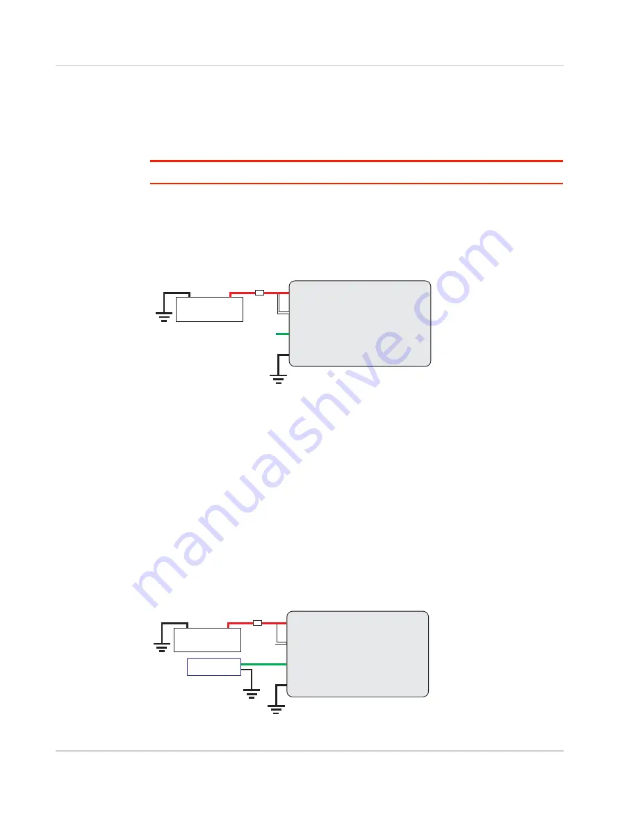
For installations using DC power, connect the wires as shown in the figure below. You can
configure Low voltage disconnect to force the router into Standby mode when the voltage
is low. Voltage is monitored on Pin 1 (red wire).
Figure 2-9: Fixed Installation without I/O
•
Pin 1 (Power) —Use the red wire in the DC cable to connect Pin 1 to the power
source. Include a 4 A, fast blow fuse, recommended to have no more than ±10% de-
rating over the operating temperature range, in the input power line. Sierra Wireless
recommends using a continuous (unswitched) DC power source.
•
Pin 2 (Ground)—Use the black wire in the DC cable to connect Pin 2 to ground. See
also
Step 2—Mount and Ground the LX40 Chassis
•
Pin 3 (On/Off control)—Connected to power
Basic Installation with I/O Input Triggered by Standby Mode
If you want to use the I/O to monitor an external device such as a motion detector, remote
solar panel, or a remote camera, refer to
. You can configure the I/O line to
wake the router up for a configured length of time, and use low voltage disconnect to put
the router in Standby mode if the voltage falls below a configured value.
Figure 2-10: Fixed Installation with I/O
LX40 router
Power
Ignition Sense
I/O
Ground
DC power source
1
3
4
2
7.5 A Fuse
LX40
DC Power Source
2 Ground
4 I/O
1 Power
3 On/Off
4 A fuse
LX40 router
Power
Ignition Sense
I/O
Ground
Motion sensor
DC power source
1
3
4
2
7.5 A Fuse
LX40
DC Power Source
2 Ground
4 I/O
1 Power
3 On/Off
4 A fuse
Motion Sensor


