background image

Installation

2 - 3

Siemens AG

SPR2-130.814.01

Page 3 of 14

SIREMOBIL Compact

Medical Solutions

Rev.01_V 03.01

TD PS 24

System Manual


Installation of the printer in the monitor trolley

2

Pull out the two guide rails completely to the front.

Place the printer on the two guide rails. 

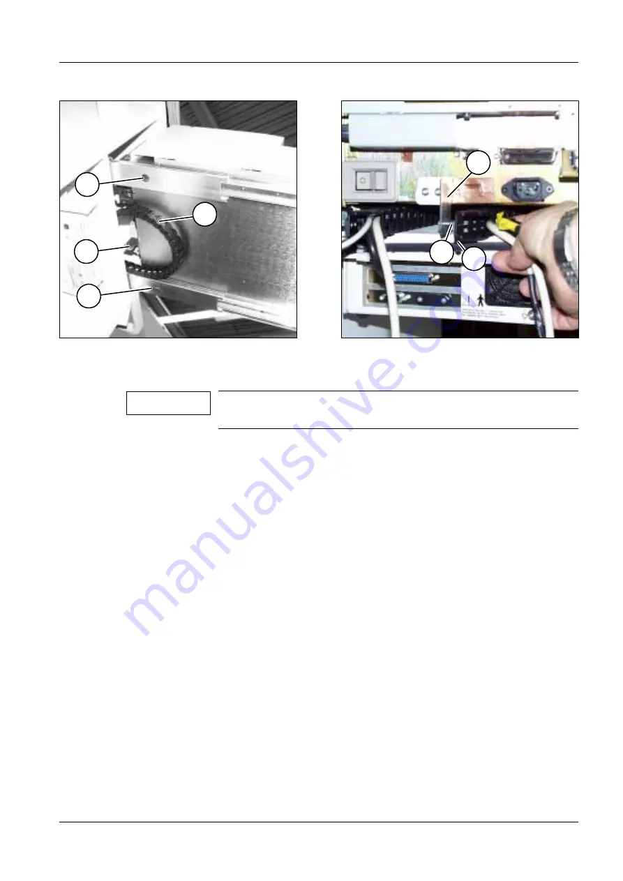
Fig. 4 shows the two drawn-out guide rails with the attached printer from below.

Place the power chain (1/Fig. 4) in a semicircle around the angle bracket (2/Fig. 4).

Secure the printer to the rails with the 12 screws supplied.

The 3 rear threads on each of the rails can be accessed by pushing the printer through 
the openings (3/Fig. 4).

Push the printer all the way into the monitor trolley and at the same time guide the power 
chain through to the rear.

Attaching the power chain

2

Attach the bracket (2/Fig. 5) at the printer with two screws.

Unscrew the two screws (1/Fig. 5) from the angle bracket (2/Fig. 5).

Attach the power chain (3/Fig. 5) to the bracket (2/Fig. 5) with the two screws (1/Fig. 5).

Fig. 4

Fig. 5

One person should hold the printer to make sure it does not fall, 
while a second person tightens the screws.

2

3

1

3

1

2

3

NOTICE

Summary of Contents for SIREMOBIL Compact CODONICS EP 1660

Page 1: ... transmission or use of this document or its contents is not permitted without express written authority Offenders will be liable for damages All rights including rights created by patent grant or registration of a utility model _or_ design _are_ reserved SP System Manual Installation Instructions CODONICS Printer EP 1660 ...

Page 2: ...SIREMOBIL Compact SPR2 130 814 01 Page 2 of 4 Siemens AG System Manual Rev 01 03 01 TD PS 24 Medical Solutions 0 2 Revision Chapter Page Revision 1 all 01 2 all 01 3 all 01 4 all 01 5 all 01 ...

Page 3: ...h 2 5 Installation when upgrading in the field 2 6 Replacing fuse F5 2 6 Checking or replacing fuse F5 2 6 Installation of the guide rails including the fan and the installation plate of the framegrabber in the monitor trolley 2 7 Unpacking the printer 2 8 Unpacking the framegrabber 2 8 Installing the framegrabber in the monitor trolley 2 9 Installation of the printer in the monitor trolley 2 10 A...

Page 4: ...s Programming the external exposure release 3 3 MEMOSKOP Video singals at hardcopy output 3 4 Read out of the actual video frequency 3 4 Memoskop SMPTE test image selection 3 4 Automatic sizing with existing 50 60 Hz monitors 3 6 Programming the film type on the printer 3 6 Testing the image quality 3 7 Final work 3 9 Page ...

Page 5: ... all covers have been fitted the protective conductor test must be carried out in accordance with ARTD 002 731 17 The protective conductor resistance must not exceed 0 2 Ohms Required documents 1 Required measuring equipment 1 Required tools 1 Operating Instructions Codonics Printer Framegrabber System Folder for Basic Unit Densitometer X RITE 331 97 02 416 Y1996 Protective conductor meter or 44 1...

Page 6: ...SIREMOBIL C SPR2 130 814 01 Page 2 of 2 Siemens AG System Manual Rev 01 03 01 TD PS 24 Medical Solutions 1 2 General This page intentionally left blank ...

Page 7: ...y The cables for the video printer are already installed in the monitor trolley Unpacking the printer 2 Turn the box with the printer upside down and open the bottom of the box Remove the foam material Remove the plastic bag Unscrew the wooden base plate Lift the printer carefully out of the box and place it on the floor in the upright position Turn the two transport locks into vertical position a...

Page 8: ...c bag Installing the framegrabber in the monitor trolley 2 Remove the large rear cover from the monitor trolley Remove the framegrabber from the packaging Remove the front and rear screws on both sides of the framegrabber cover 1 Fig 2 Insert the framegrabber from the front in the fixing bracket and secure laterally to the fixing bracket with the lock washers and knurled screws supplied 1 Fig 3 Th...

Page 9: ...he printer to the rails with the 12 screws supplied The 3 rear threads on each of the rails can be accessed by pushing the printer through the openings 3 Fig 4 Push the printer all the way into the monitor trolley and at the same time guide the power chain through to the rear Attaching the power chain 2 Attach the bracket 2 Fig 5 at the printer with two screws Unscrew the two screws 1 Fig 5 from t...

Page 10: ...he 9 pin SUB D HAND CTRL socket and secure it with screws Run the cable from the hand held control unit to the cable holder 1 Fig 6 and secure it with a cable tie Wiring the printer 2 Insert the connector from the power cable in the power socket of the printer 2 Fig 6 The other end of the power cable is already connected to the ON OFF assembly terminal block X2 1 X2 2 and the protective conductor ...

Page 11: ...rabber 10 Fig 6 Wiring the framegrabber video cable 2 Connect one end of the video cable to the 15 pin SUB D socket of the framegrabber 8 Fig 6 With no additional video components present e g a video recorder Run the other end of the video cable through the duct 14 Fig 6 to the MEMOSKOP Plug the BNC connector to the OUT3 socket of the MEMOSKOP and lock With video recorder present Run the other end...

Page 12: ... F5 2 Check the value of fuse F5 on board D50 of the ON OFF assembly installed in the bottom shelf of the monitor trolley If a 4 AT fuse is fitted replace it with the 6 25 AT fuse supplied On board D50 stick the label 6 25 AT supplied on top of the fuse label 4 AT Manually change the fuse value of the F5 fuse to 6 25 AT in the wiring diagram Enter the remark Condonics printer installed together wi...

Page 13: ...g 8 The threaded holes of the installation plate are also exactly below the drill holes 1 Fig 7 Attach both fan plates 1 Fig 8 to the installation plate of the framegrabber 2 Fig 8 with the 4 screws Lock washers are not required since the screws supplied are coated with Loctite Place the two guide rails Fig 9 on the two plates 1 Fig 8 The rails can be pulled out towards the front The attachment ho...

Page 14: ...n base plate Lift the printer carefully out of the box and place it on the floor in the upright position Turn the two transport locks into vertical position and pull out in vertical position Fig 10 Unpacking the framegrabber 2 Open the packaging of the framegrabber from the top Remove the framegrabber and the hand held control unit Remove the plastic bag Fig 9 Fig 10 Keep the two transport locks I...

Page 15: ...ey 2 Remove the framegrabber from the packaging Remove the front and rear screws on both sides of the framegrabber cover 1 Fig 11 Insert the framegrabber from the front in the fixing bracket and secure laterally to the fixing bracket with the lock washers and knurled screws supplied 1 Fig 12 The fan and the connections of the framegrabber point to the rear Fig 11 Fig 12 1 1 1 1 ...

Page 16: ...printer to the rails with the 12 screws supplied The 3 rear threads on each of the rails can be accessed by pushing the printer through the openings 3 Fig 13 Push the printer all the way into the monitor trolley and at the same time guide the power chain through to the rear Attaching the power chain 2 Attach the bracket 2 Fig 14 to the printer with two screws Unscrew the two screws 1 Fig 14 from t...

Page 17: ...ble with the free cable ends from the power chain to the lateral duct 13 Fig 15 up to the ON OFF assembly Connect the two ends bn and bl of the power cable to terminal blocks X2 1 and X2 2 Connect the protective conductor ye gn of the power cable to the protective conductor terminal Insert the connector from the power cable in the power socket of the printer 2 Fig 15 Insert the control cable in th...

Page 18: ...er control cable is already connected to the printer The printer control cable is fed to the framegrabber via the power chain and has a 25 pin SUB D connector at the second cable end Connect the 25 pin SUB D connector to the Printer socket of the framegrabber 10 Fig 15 Wiring of the framegrabber video cable 2 Connect one end of the video cable to the 15 pin SUB D socket Video In of the framegrabbe...

Page 19: ...ber 12 Fig 15 Load the film cassette with film screens and insert to the printer Replacing the rear cover of the monitor trolley 2 Unscrew the protective conductor of the existing rear cover of the monitor trolley Unpack the new rear cover Screw the protective conductor onto the new rear cover If the new rear cover does not contain cable holders unscrew the cable holders of the old rear cover and ...

Page 20: ...SIREMOBIL Compact SPR2 130 814 01 Page 14 of 14 Siemens AG System Manual Rev 01 03 01 TD PS 24 Medical Solutions 2 14 Installation This page intentionally left blank ...

Page 21: ...for stored subtraction scenes With all other Memoskop memories negative image display must be activated by the cus tomer each time after switching on the equipment by simultaneously pressing CTRL R With Memoskops that have no keyboard changeover is therefore not possible We recommend using positive image display If the customer explicitly requires negative image display programming according to th...

Page 22: ...he Miscellaneous menu line with the cursor key or and press the OK Enter key Select the Set Date Time menu line with the cursor key or and press the OK Enter key The date format as well as the date and time can now be changed Selected menus can be closed again with the Erase Cancel key Changes of values parameters previously confirmed by OK Enter are taken over Press the Menu key to return to the ...

Page 23: ...e release 3 To enable the framegrabber to evaluate the print key on the Memoskop and SIREMOBIL basic unit and to print an image this function must be programmed The Installation menu is already selected See Enabling the Framegrabber Service Modes If not select the INSTALLATION menu line with the cursor key or and press the OK Enter key Select the Exam ID Config menu line with the cursor key or and...

Page 24: ...ard is available connect the Service PC to the system and start the MEMOSKOP service program In the main menu press the Get from Memoskop button Call up the Others menu read out the video frequency and note down Do not exit the Technical Setup yet Memoskop SMPTE test image selection 3 Select LUT 1 for both monitors on the MEMOSKOP keyboard or on the basic unit Call up the SPMPTE test image on the ...

Page 25: ...ress the OK Enter key 4 selection menus are available Select the appropriate line with the cursor key or and press the OK Enter key Do not perform for 60Hz video frequency and preferred positive image display factory default settings Menu Video frequency Image polarity Description Siremobil C NTSC 60 Hz or 120 Hz Positive Factory setting Siremobil C PAL 50 Hz or 100 Hz Positive for 50 Hz or 100 Hz...

Page 26: ...at the beginning of the line Select the Automatic Sizing menu line with the cursor key or and press the OK Enter key Confirm the Automatic Sizing Proceed query with the OK Enter key Press the Menu key to select the main menu again Programming the film type on the printer 3 Insert the film supplied in the film compartment of the printer Program the film type See operating instructions section Loadi...

Page 27: ...ge display expose a film and measure the density in the fields 0 40 and 100 enter in Table 1 and compare with the reference values below Table 1 Reference values with programmed positive image display Gray scale Minimum density Nominal density Maximum density Actual values 0 2 7 2 9 3 1 10 2 1 2 28 2 46 n a 20 1 64 1 81 1 98 n a 30 1 33 1 48 1 63 n a 40 1 06 1 2 1 34 50 0 84 0 96 1 08 n a 60 0 65 ...

Page 28: ...40 and 100 enter in Table 2 and compare with the reference values below Table 2 Reference values with programmed negative image display Gray scale Minimum density Nominal density Maximum density Actual values 0 0 16 0 21 0 26 10 0 20 0 27 0 35 n a 20 0 32 0 42 0 52 n a 30 0 53 0 65 0 78 n a 40 0 85 1 0 1 15 50 1 28 1 45 1 63 n a 60 1 70 1 90 2 10 n a 70 2 04 2 26 2 49 n a 80 2 31 2 56 2 81 n a 90 ...

Page 29: ...PS 24 System Manual Final work 3 File the installation and configuration instructions in the system manual Refit all covers Carry out the protective conductor test in accordance with ARTD 002 731 17 The protective conductor resistance must not exceed 0 2 Ohms Hand over the operating instructions to the customer ...

Page 30: ...SIREMOBIL Compact SPR2 130 814 01 Page 10 of 10 Siemens AG System Manual Rev 01 03 01 TD PS 24 Medical Solutions 3 10 Commissioning This page intentionally left blank ...

Reviews: