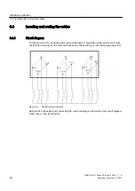
The connecting cables of the temperature sensors are routed to the main or auxiliary terminal
box, depending on the version. The connection and assignment of the terminals is specified
in the circuit diagram.
WARNING
Hazard due to electric shock
The installation of the temperature sensors for the winding monitoring with respect to the
winding is implemented according to the requirements for basic insulation. The temperature
sensor connections are located in terminal boxes, safe to touch, and have no protective
separation. This is the reason that in the case of a fault, a hazardous voltage can be present
at the measuring sensor cable. When touched, this can result in death, severe bodily injury
and material damage.
● When connecting the temperature sensor to external temperature monitoring devices,
when required, apply additional measures to fully comply with the requirements set out in
IEC 60664-1 or IEC 61800-5-1 "Hazard due to electric shock”.
6.5.4
Internal equipotential bonding in the auxiliary terminal box
The equipotential bonding between the PE terminals in the relevant auxiliary terminal box
enclosure and the machine enclosure is established via a fixing bolt in each auxiliary terminal
box enclosure. The contact point underneath the bolt head is bare metal and protected against
corrosion.
WARNING
Ineffective equipotential bonding
If the equipotential bonding connection fails, parts of the machine may become live. If you
touch them, you will receive an electric shock. This can result in death, serious injury or
material damage.
● When performing any installation work you must always take care to ensure that all
equipotential bonding connections remain effective.
Electrical connection
6.5 Connecting the auxiliary circuits
SIMOTICS HT Series HT-direct 1FW4...1......A
Operating Instructions 11/2018
75
Summary of Contents for SIMOTICS HT Series
Page 2: ...13 11 2018 16 25 V5 00 ...
Page 10: ...Table of contents SIMOTICS HT Series HT direct 1FW4 1 A 10 Operating Instructions 11 2018 ...
Page 26: ...Description SIMOTICS HT Series HT direct 1FW4 1 A 26 Operating Instructions 11 2018 ...
Page 118: ...Service and Support SIMOTICS HT Series HT direct 1FW4 1 A 118 Operating Instructions 11 2018 ...
Page 122: ...Quality documents SIMOTICS HT Series HT direct 1FW4 1 A 122 Operating Instructions 11 2018 ...
Page 127: ......


