2-8
SIMATIC TD 200 Operator Interface
C79000-G7076-C272-01
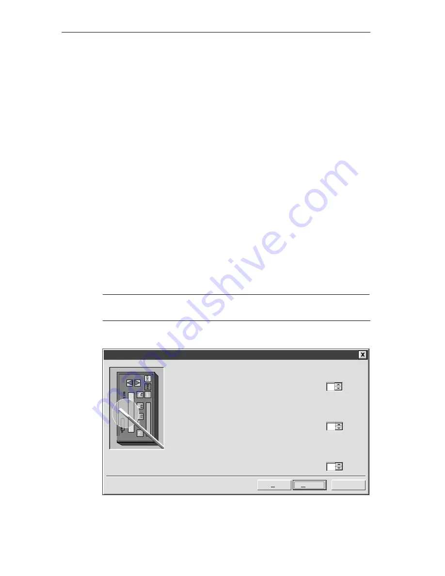
Specifying Parameter Block Address, Message Enable Address, and Message Location
You can specify the starting addresses for the parameter block, the message
enable flags, and the messages (Figure 2-7).
The TD 200 looks for a parameter block in the V memory of the CPU. The default
location for the parameter block is VB0. See Section 3.8 and Section D.1 for more
information about changing the location of the parameter block.
The starting byte for the message enable flags defines the location in V memory at
which the message enable flags begin. The default location is 14. There are eight
message enable flags stored in each byte. Whole bytes must be allocated for
message enable flags even if all the bits are not used. The “Starting byte for
enable flags” field specifies how many bytes of V memory are needed for message
enable flags (based on the number of messages you previously set in Figure 2-6).
The starting byte for message information defines the starting location of the first
message in V memory. Messages are placed consecutively in memory. Either 20
or 40 bytes are reserved for each message.
Values for the parameter block, enable flags, and message information starting
addresses are CPU-specific. See the
SIMATIC S7-200 Programmable Controller
System Manual for the valid address ranges for specific CPUs.
For this example, set the parameter block starting byte to 0, the enable flags
address to 14, and the message information starting address to 40 as shown in
Figure 2-7.
Note
Refer to Appendix E if you are changing an existing TD 200 configuration.
TD 200 Configuration Wizard
Cancel
Next >
You must define where the 14 byte parameter definition will be placed in the
data block. It is usually located at VB0.
< Prev
0
Starting byte for 14 byte parameter block:
14
Starting byte for enable flags:
40
Starting byte for message information:
You have defined 3 messages requiring 1 byte(s) for message enable flags.
You must now define where the enable flags will reside in the data block.
You have defined 3 messages requiring 120 consecutive bytes for the
message information. You must define where the message information is to
reside in the data block.
TD200
Figure 2-7 Wizard: Block Address, Enable Flags, and Message Location
Configuring the TD 200
Summary of Contents for SIMATIC TD 200
Page 22: ...1 12 SIMATIC TD 200 Operator Interface C79000 G7076 C272 01 Product Overview and Installation ...
Page 84: ...A 12 SIMATIC TD 200 Operator Interface C79000 G7076 C272 01 Specifications and Reference ...
Page 94: ...B 10 SIMATIC TD 200 Operator Interface C79000 G7076 C272 01 Multiple CPU Configurations ...
Page 126: ...E 6 SIMATIC TD 200 Operator Interface C79000 G7076 C272 01 Modifying a TD 200 Configuration ...


