Interval Counter Input
4-8
SM 335 – High-Speed Analog Input/Output Module for the SIMATIC S7-300
6ES7 335-7HG00-8BA1
4.5
Interval counter values
Address
The values, which the SM 335 computes for the pulse input, are stored at the I/O
address module start a 12.
Table 4-2
Pulse input values
Module address
Content
+ 12
Interval counter
+ 13
Interval duration, byte 1
+ 14
Interval duration, byte 2
+ 15
Interval duration, byte 3
Interval counter (module a 12)
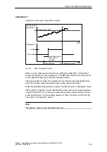
The interval counter is a ring counter in the range 0 to 255. The first pulse to arrive
initializes the counter internally. When the second pulse arrives, the counter is in-
cremented by ’1’. Each subsequent pulse increments the counter by ’1’.
The SM 335 stores the number of intervals acquired to date in the data byte at
“module a 12”. This data byte is ’0’ as long as no interval has been detec-
ted. Each time an interval is detected, the counter is incremented by ’1’.
Interval duration (module a13 to 15)
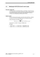
During an interval, the SM 335 counts the time until the interval ends in incre-
ments, or time slices, of 0.5
m
s. The SM 335 enters the duration of the interval in
three bytes, beginning with the byte at “module start a 13”.
The byte at “module start a 13” is of a higher order than the byte at “mod-
ule start a 14”. The byte at “module start a 15” has the lowest
order of all.
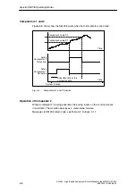
Overflow
If an interval is longer than 16777215 (FF FF FF
in hexadecimal
) times 0.5
m
s
(8.3886075 s), the SM 335 interprets it as an overflow rather than as an interval.
The value for the interval duration is left at ’FF FF FF
in hexadecimal
’, and the interval
counter stops. When the next pulse arrives, the interval duration is measured once
again and, if it is of valid duration, the interval counter is again incremented by ’1’.


