Connecting the Inputs and Outputs of the SM 335
2-5
SM 335 – High-Speed Analog Input/Output Module for the SIMATIC S7-300
6ES7 335-7HG00-8BA1
2.3
Connecting the analog outputs
Connecting the analog outputs
The analog outputs must be connected as voltage outputs. Detailed informa-
tion can be found in the SIMATIC Programmable Logic Controller, S7-300 Module
Data Reference Manual.
Recommendation
If possible, the SM 335’s analog outputs, with the associated zero potential, should
be connected to a terminal block from where you can tap the zero potential for the
analog outputs.
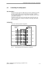
Configuration
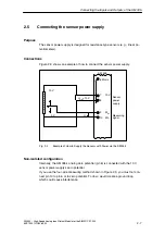
The result is the following basic configuration:
Twisted-pair,
shielded
Actuator 0
Actuator 1
Actuator 2
Actuator 3
SM 335
M
ANA
6
CH3 5
CH0 2
CH1 3
CH2 4
Fig. 2-2
Connecting Actuators to the SM 335
Non-Isolated
Actuators, which are shielded and whose shields are grounded and connected to
the actuator’s zero potential conductor, form a ground loop. You must therefore
break the connection between shield and zero potential conductor on the actuator
or use an actuator whose zero potential conductor is not connected to ground.


