Data Exchange with the SM 335
3-26
SM 335 – High-Speed Analog Input/Output Module for the SIMATIC S7-300
6ES7 335-7HG00-8BA1
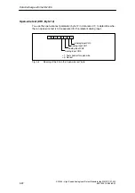
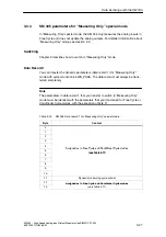
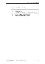
Comparator 1 and Comparator 2 (DR1, bits 12.6 + 12.5)
You switch Comparator 1 and 2 on with the Comparator 1 and 2 bits
(see Table 3-14).
Table 3-14
Checking the comparator with check bits 1 and 2
Bit 6
Bit 5
Behavior of the comparator
1
1
Switch on Comparators 1 and 2 in succession
0
1
Switch on Comparator 2
1
0
Switch on Comparator 1
0
0
“Comparator” mode exited immediately.
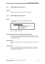
Hardware interrupt (DR1, bit 12.4)
If you set bit 4 in the comparator check byte to ‘1’, the SM 335 generates a hard-
ware interrupt at the reversing point.
Comparator 1 to Comparator 2 Reversing Point
Comparator 1 is monitored in the Free and Conditional Cycles. If the measuring
value has reached or exceeded the Comparator 1 value and a Comparator 2 has
been defined, only the Comparator 2 channel is cyclically measured (approximately
every 40
µ
s) from the reversing point.
If the measuring value has reached or exceeded the Comparator 2 value, or the
parameterized monitoring time (max. 8.3 seconds) is exceeded, the Free or Condi-
tional Cycles continue.
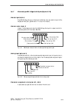
Analog output (DR1, Bit 12.3 to 12.0)
In bits 0 to 3 of the comparator check byte (DR1, byte 12, see Figure 3-7), you
specify the analog outputs that the analog values specified in DR1 (byte 0 to 5 in
Table 3-13) are to be output to.
•
Bit i
=
1: Specified value is output
•
Bit i
=
0: Old analog value is retained
You can set up to 3 bits. The analog values are output until a new value is written
to the output.


