97BPLC concepts
4.3 Processing of analog values
S7-1200 Programmable controller
System Manual, 11/2011, A5E02486680-05
85
Configuring the I/O in the CPU and I/O modules
When you add a CPU and I/O modules to your
configuration screen, I and Q addresses are
automatically assigned. You can change the
default addressing by selecting the address field in
the configuration screen and typing new numbers.
Digital inputs and outputs are assigned in
groups of 8 points (1 byte), whether the module
uses all the points or not.
Analog inputs and outputs are assigned in
groups of 2 points (4 bytes).
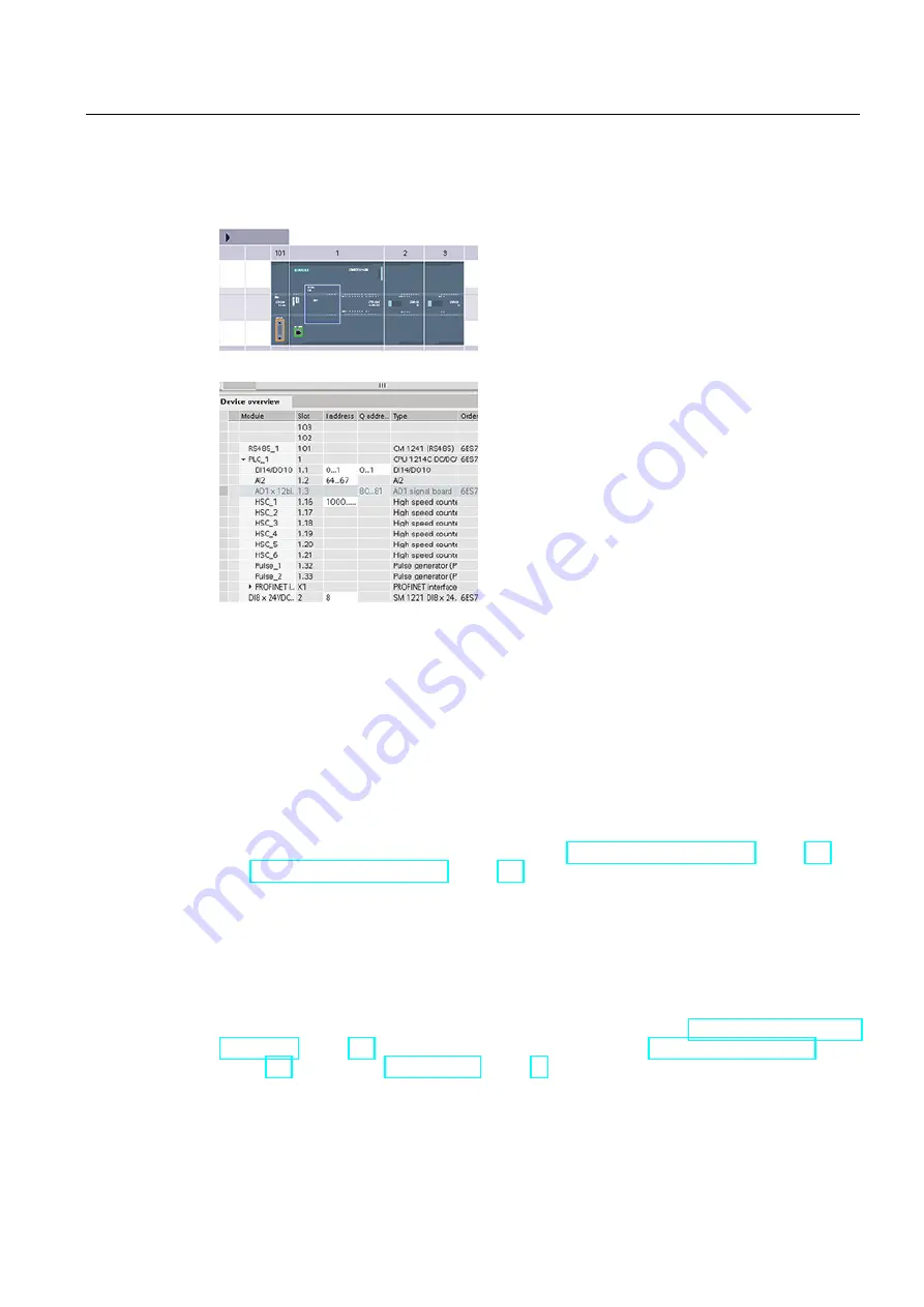
The figure shows an example of a CPU 1214C with two SMs and one SB. In this example,
you could change the address of the DI8 module to 2 instead of 8. The tool will assist you by
changing address ranges that are the wrong size or conflict with other addresses.
4.3
Processing of analog values
Analog signal modules provide input signals or expect output values that represent either a
voltage range or a current range. These ranges are ±10V, ±5V, ±2.5V, or 0 - 20mA. The
values returned by the modules are integer values where 0 to 27648 represents the rated
range for current, and -27648 to 27648 for voltage. Anything outside the range represents
either an overflow or underflow. See the tables for analog input representation (Page 708)
and analog output representation (Page 708) for details.
In your control program, you probably need to use these values in engineering units, for
example to represent a volume, temperature, weight or other quantitative value. To do this
for an analog input, you must first normalize the analog value to a real (floating point) value
from 0.0 to 1.0. Then you must scale it to the minimum and maximum values of the
engineering units that it represents. For values that are in engineering units that you need to
convert to an analog output value, you first normalize the value in engineering units to a
value between 0.0 and 1.0, and then scale it between 0 and 27648 or -27648 to 27648,
depending on the range of the analog module. STEP 7 provides the NORM_X and SCALE_X
instructions (Page 206) for this purpose. You can also use the CALCULATE instruction
(Page 186) to scale the analog values (Page 30).


