Module Replacement
2.2.2 Accessing Modules on the Bottom Row
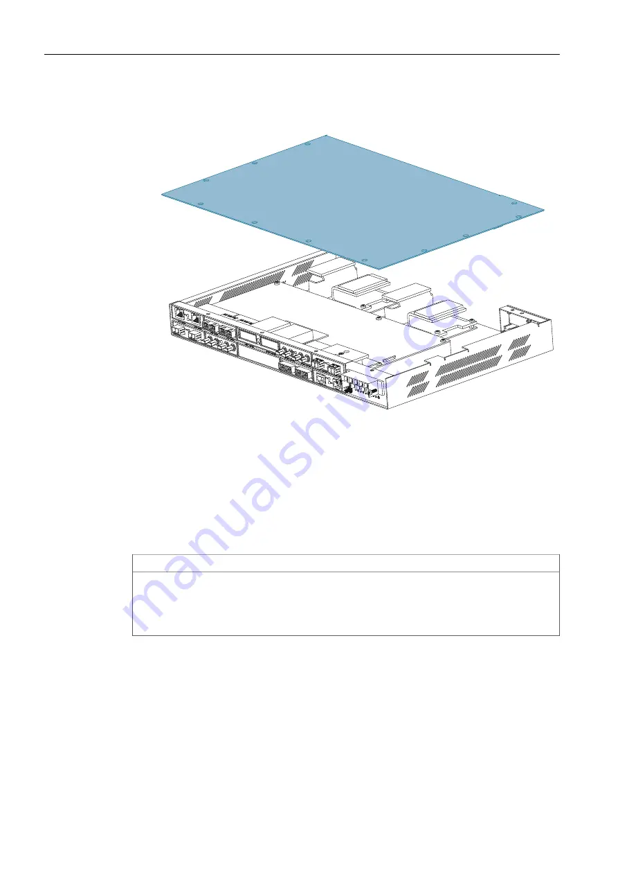
8. Remove the cover and set it aside temporarily.
Figure 2.4
Removing the Cover
2.2.2
Accessing Modules on the Bottom Row
If the module you want to replace is in slot 2, 4, 6, 8, or 10 along the bottom row,
the main inner assembly needs to be partially removed to gain access.
To partially remove the main inner assembly, do the following:
NOTICE
Environmental hazard – risk of damage to the device
Protect modules, connectors, and wiring from dirt, heat, static electricity, and mois-
ture. Have connector covers available and wear appropriate ESD protective equip-
ment.
1. Carefully flip the device over to expose the screws that secure the main inner as-
sembly to the chassis.
RUGGEDCOM RSG2100
Service Manual, 07/2019, C79000-G8976-1151
11


