


70
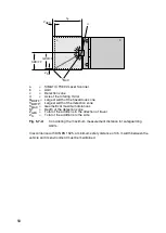
a
=
Fuse 1.25 A, semi time-lag
d
=
DZ 2/WF 2
b
=
Restart button
e
=
DZ 3/WF 3
c
=
DZ 1/WF 1
f
=
DZ 4/WF 4
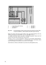
Fig. 8.1-2:
Wiring the SIMATIC FS600 Laser Scanner with evaluation of the OSSDs,
zone pair changeover, restart interlock and static relay monitoring
Relays K1 and K2 must have forced contacts. They are operated directly at the two
failsafe semiconductor outputs OSSD 1 (X1-12) and OSSD 2 (X1-11).
A suitable mechanism must be provided for extinguishing sparks. Please note that
doing this will cause the switching time to be extended.
Channels “x” and “y” must be integrated for Category 3 in accordance with DIN EN 954-
1. Integrating one channel based on “z” is only permitted with a one-channel control
system and taking into consideration the results of a risk analysis.
Serial machine controls are admissible only insofar the valid regulations allow.
1 2 3 4 5 6 7 8 9 10 11 12 13 14 15
K1
K2
K1
K2
+24 V
GND
PE
a
b
c
d e f
X1
x
x
K2
y
y
K1
z
z
K2
K1
SIMATIC FS600 Laser Scanner
Summary of Contents for SIMATIC FS600
Page 2: ...600672 ...
Page 109: ...109 ...


