background image

04/99

Displaying and Entering Values in Screens

Getting Started with C7-621-AS-i

41

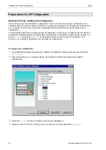
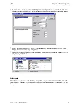
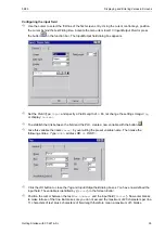
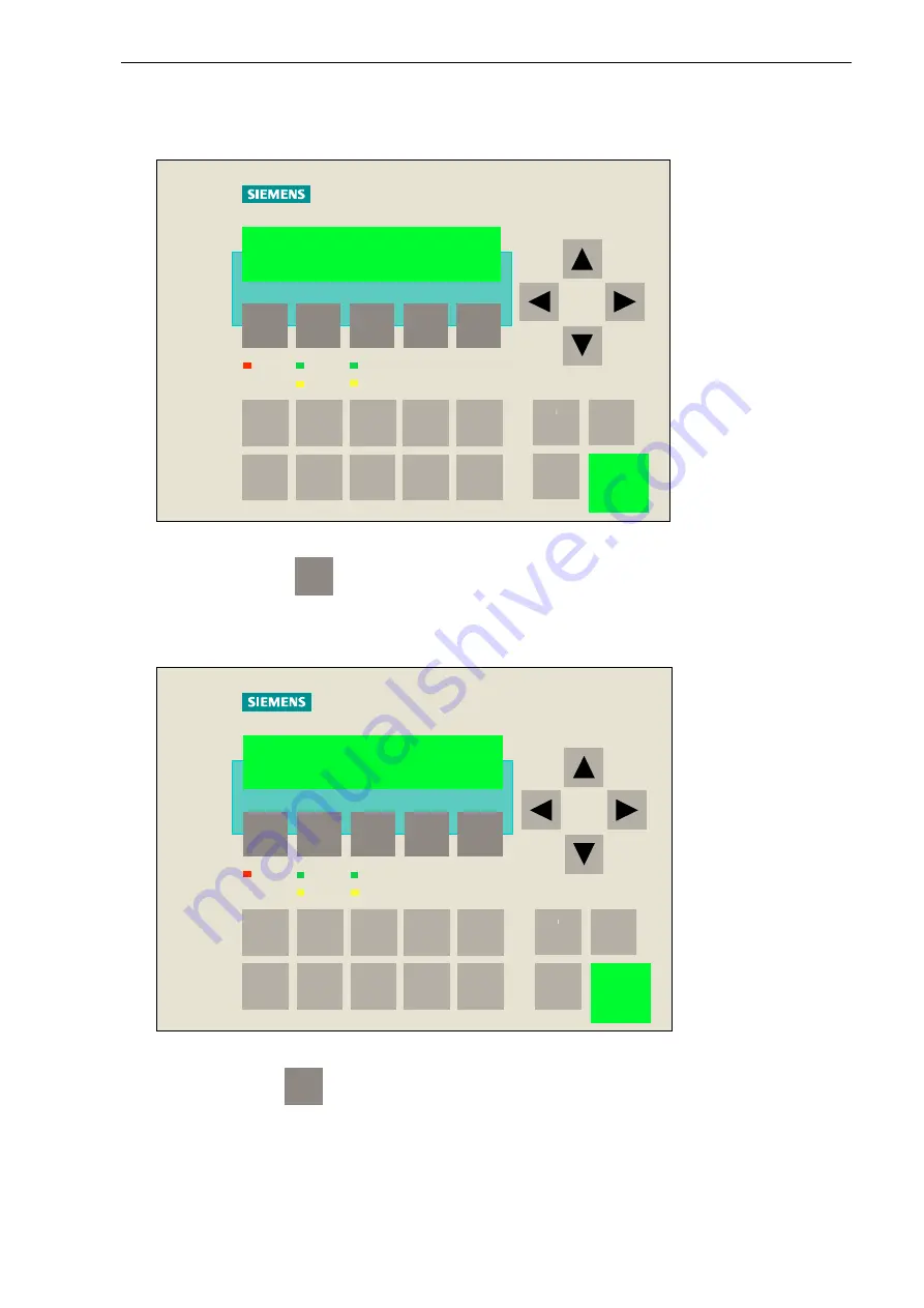
Once the transfer is complete, the C7 starts up. When you press the

ENTER

key, the start screen is

displayed.

F1

F2

F3

F4

F5

SF

DC5V

FRCE

RUN

STOP

1

2

3

7

8

9

6

4

5

0

SIMATIC C7-621

ENTER

ESC

S H IF T

+/-

System_1

Pak

Activate the softkey

F5

to reach the system screen.

Enter a value in the input field.

F1

F2

F3

F4

F5

SF

DC5V

FRCE

RUN

STOP

1

2

3

7

8

9

6

4

5

0

SIMATIC C7-621

ENTER

ESC

S H IF T

+/-

Max.number:

8

Back

>>

Activate the softkey

F5

to reach the second screen entry. Now check the functionality of

your inductive proximity switch including the count function.

Summary of Contents for simatic c7-621

Page 1: ...Getting Started with C7 621 AS i 1 SIMATIC SIMATIC C7 621 AS i Control System First steps with STEP 7 Mini and ProTool Lite Guide Edition 07 1999 ...

Page 2: ......

Page 3: ...ks 26 1 st option Loading all blocks 26 2 nd option Loading individual blocks 26 Program extension 26 Saving RAM to ROM 29 Preparations for OP Configuration 30 Starting ProTool creating the configuration 30 Online Help 31 Displaying and Entering Values in Screens 32 Configuring texts 32 Transferring the configured data 33 Extending the configuration 34 Linking and branching between screens via sof...

Page 4: ... I O extension Interface for connecting an expansion unit Can control up to 31 slaves Up to 248 binary elements AS Interface master F1 F2 F3 F4 F5 SF DC5V FRCE RUN STOP Hello I am the smallest SIMATIC C7 1 2 3 7 8 9 6 4 5 0 SIMATIC C7 621 ENTER ESC SHIFT SIMATIC S7 300 SIEMENS COROS OP3 ENTER ESC SHIFT F2 F3 F4 F5 F1 1 2 3 4 5 6 7 8 9 0 ...

Page 5: ... tasks on a sample system and further tips and tricks All chapters are structured as follows Þ First the task is explained Þ Then the individual solution steps are described with the help of selected dialog boxes Þ Finally we show you the result so that you can check your own result immediately after each programming configuring step Conventions A mouse indicates that entries are to be made on the...

Page 6: ...21 AS i control system 6ES7 621 6BD00 0AE3 yes 7 24V power supply PS307 6ES7 307 1BA00 0AA0 no 8 AS Interface power pack and AS i cable 3RX9307 0AA00 yes 9 2 x connecting cable with M 12 socket and connector 3RX1634 yes 10 Position switch with AS i connection 3SE3230 1GW Z Z C01 yes 11 Inductive proximity switch 3RG4022 3JB00 yes 12 Optical proximity switch 3RG7130 3AB00 yes 13 SIGNUM casing with ...

Page 7: ... STEP 7 Mini on PC programming device Þ Connect C7 to power supply 24V Þ Connect power pack to C7 AS i port Þ Set up AS i network Þ Set addresses of slaves and parameterize C7 AS i CP Þ Select STEP 7 Mini on programming device PC and create PLC program Þ Connect C7 PC programming device via PC MPI cable Þ Overall reset of C7 CPU and C7 OP Þ Transfer PLC program to C7 Þ Select ProTool Lite on progr...

Page 8: ...ted to the relevant ejectors on conveyor belts The current location of the parcels is recorded via sensors and transmitted to the SIMATIC via AS i The PLC processes this data and controls connected actuators via the AS Interface On the basis of the sample machine you will learn how to handle the AS i functions step by step You will set up an AS i network program a PLC program and learn how to esta...

Page 9: ...emory in the slave On delivery all slaves have the address zero by default Each slave in the network must have a unique address that is not zero The C7 621 AS i allows you to change the set address of a slave through operation on the C7 When using the C7 addressing function it is therefore necessary to connect all new slaves to the AS i cable consecutively to ensure that they are each assigned a u...

Page 10: ...he password is preset to 100 Enter the digits 100 via the numeric keypad and confirm your input with ENTER Select the operating mode STOP To quit the mask press the ESC key once Now press the F5 key to display the start menu for the individual AS i functions Status Project Version In the start menu for the AS i functions select Project by pressing F4 once AUTOPROG Config Address For setting addres...

Page 11: ...by pressing the F3 key Enter the old address in the first field and the new address in the second field Old 00 New 01 Set Adr Press F4 to confirm your entry If you have made all the entries and settings correctly the message NO_ERROR will appear in the display of the C7 621 AS i control system Press F5 to complete the current addressing process Connect the next slave to your AS i shaped cable acco...

Page 12: ... twice Accept the actual configuration recognized by the system as the setpoint configuration To do this press F4 again to call the menu for setting the setpoint configuration If you wish you can view the actual configuration again by pressing F2 To close the display press ESC Press F4 to accept the current actual configuration as the setpoint configuration Press F5 to confirm the NO_ERROR message...

Page 13: ...anager Once STEP 7 is started terminate the STEP 7 Assistant New Project Online Help If there is anything you are unsure of during programming or if you want further information on specific points press F1 This starts the Online Help in which you will find explanations of the various STEP 7 topics General settings Before you start programming you need to select one of two mnemonic options in the S...

Page 14: ...ce To do this select the menu item Options Set PG PC Interface Set the PC Adapter MPI in the dialog box that appears If the PC Adapter is not displayed in the window you can install it now Activate the Install button and follow the instructions Enter the following settings as the PC programming device interface Properties ...

Page 15: ... with OK You can now start to create your project Creating a project Select the menu item File New In the dialog box that appears create a new project with the name GetStart Assign a hardware item to your project with the menu item Insert Station 2 SIMATIC 300 Station The SIMATIC 300 Station 1 folder appears Overwrite the name of this station with the new name Systen_1 ...

Page 16: ...the Hardware Catalog via Insert Hardware Compo nents Mark here the C7 621 AS i via SIMATIC 300 C7 to display brief information on the control station Double click on C7 621 AS i to insert the device into slot 2 in the Hardware Configuration window Here you will see information on the set MPI address of the C7 CPU default setting for the MPI address is 2 and an address map To save the configuration...

Page 17: ...k on the tab sheet Cycle Clock Memory to select it Þ Activate the Clock Memory checkbox and enter 10 for the number of the memory byte Each bit of the clock memory byte is assigned a period time frequency Bit 7 6 5 4 3 2 1 0 Period time s 2 1 6 1 0 8 0 5 0 4 0 2 0 1 Frequency Hz 0 5 0 625 1 1 25 2 2 5 5 10 Confirm your entries with OK To save the configuration select Station Save and Compile from ...

Page 18: ... 20 Slave 21 259 Slave 6 Slave 7 267 Slave 22 Slave 23 260 Slave 8 Slave 9 268 Slave 24 Slave 25 261 Slave 10 Slave 11 269 Slave 26 Slave 27 262 Slave 12 Slave 13 270 Slave 28 Slave 29 263 Slave 14 Slave 15 271 Slave 30 Slave 31 Bit 3 I Bit 2 I Bit 1 i Bit 0 Bit 3 I Bit 2 I Bit 1 i Bit 0 Bit 3 I Bit 2 I Bit 1 i Bit 0 Bit 3 I Bit 2 I Bit 1 IBit 0 The parameters required in the application appear on...

Page 19: ...the desired type Accept the settings with OK Select the second entry in the Name column and enter here the name M1_In1 Complete your input by pressing Return The Type entry is automatically activated Click on the entry with the right mouse button enter the type BOOL via Elementary Types and complete your input with Return Enter FALSE as the initial value and press Return In the Comment column you ...

Page 20: ...Programming Preparations 04 99 20 Getting Started with C7 621 AS i ...

Page 21: ...ng addresses in DB1 are significant Adress Symbol Status format Meaning 0 0 M1_IN1 Bin Optical Bero 0 1 M1_IN2 Bin Inductive Bero 1 0 M3_IN1 Bin Position switch 2 0 M5_IN2 Bin ON button 2 1 M5_IN3 Bin Acknowledgment button 2 3 M5_IN1 Bin OFF button 4 0 M1_OUT1 Bin Belt ON bit memory 6 0 M5_OUT1 Bin Green lamp 6 1 M5_OUT2 Bin Red lamp 6 2 M5_OUT3 Bin White lamp ...

Page 22: ... at the end of the belt position switch inactive ejector in initial position checked by the inductive proximity switch Þ If the initial position is defined the belt is activated The movement of the belt is simulated by the LED of the output 1 of slave 1 DB1 DBX4 0 The display is only possible if auxiliary power for the outputs is supplied to the AS Interface user module Otherwise DB1 DBX4 0 has th...

Page 23: ...ment you can now insert your program lines To do this click in the white area below the gray comment field This opens a box with the current cursor position When making your entry make sure you include the relevant blanks at least one blank each as a separator between operation code operand and comment in each program line otherwise STEP 7 will not recognize the instruction and will signal this in...

Page 24: ... toolbar For an executable program you must still write the AS i input data to DB1 at the start of the cycle and the outputs from DB1 to the AS i output data at the end of the cycle To do this open OB1 in the SIMATIC Manager and insert the following networks and program lines Network 1 Route process image of AS i line to DB OPN DB1 L PIW 256 T DBW 0 L PIW 258 T DBW 2 Network 2 Call system componen...

Page 25: ...d as follows Deleting C7 CPU memory In the SIMATIC Manager select the Accessible Nodes icon In the window which appears open the folders MPI 2 and Blocks by double clicking on them Mark all OBs FBs FCs and DBs Delete the marked objects from the C7 CPU You have now deleted the load memory of the C7 CPU Mark the folder MPI 2 and copy the contents of the load memory into the C7 CPU flash memory via P...

Page 26: ...password is preset to 100 Enter the digits 100 via the numeric keypad and confirm your input with ENTER Select the operating mode RUNP again Test your program on the C7 621 AS i control system using your AS i components The functions of the system as specified in the first programming step should be set up Program extension Now you are going to extend your system The system is to work as follows Þ...

Page 27: ...counter I R C1 is reset Network 2 Parcel sequence A DB1 DBX4 0 Belt_ON A DB1 DBX0 0 Opto_Bero parcel FN M30 1 Edge formation L S5T 10S Parcel interval at least 10 seconds SE T5 Pulse extension A T5 Parcel interval too small A DB1 DBX0 0 Opto_Bero parcel FP M30 2 Edge formation S M21 1 Fault in parcel sequence Network 3 Display parcel detected A DB1 DBX4 0 Belt ON A DB1 DBX0 0 Opto_Bero DB1 DBX6 2 ...

Page 28: ...No fault M15 0 Initial position In Network 3 insert the program line O M16 0 so that the conveyor belt will be deactivated if a fault occurs Network 3 Belt OFF A DB1 DBX2 3 Belt_OFF switch on casing O M16 0 Belt OFF R DB1 DBX4 0 Output Belt_ON Save the function FC1 and overwrite the block in the CPU by reloading Finally the organization block OB1 must be adjusted In the SIMATIC Manager open the OB...

Page 29: ...MATIC Manager select the Accessible Nodes symbol again In the dialog window displayed mark the folder MPI 2 Copy the contents of the load memory into the C7 CPU flash memory via the menu item PLC Save RAM to ROM The PLC program is now stored in non volatile memory in the C7 CPU Close the Accessible Nodes window On the C7 621 AS i press F1 to change back to the operating mode RUNP The RUN LED light...

Page 30: ...your first configuration we advise you to take the second option of starting with a supplied standard configuration The standard configuration contains basic settings e g Device C7 621 Language English and standard screens for easy access to frequently used functions e g change of operating mode assignment of passwords Creating a new configuration In the SIMATIC Manager select Insert Station 8 SIM...

Page 31: ...e entered all the settings close the dialog box by activating the button OK In the Projekt Wizard confirm this step with Weiter Select Use Standard Projects and close the Project Wizard with Fertig stellen to create the Project OP_System_1 in ProTool Online Help If there is anything you are unsure of during configuration or if you want further information on specific points press F1 This starts th...

Page 32: ...e there System_1 SIMATIC C7 startup always ends automatically with a display of the configured start screen The screen you have just configured display of the text System_1 is now to be displayed after the next loading of the configuration You must therefore mark this screen as the start screen Select the menu item Edit Properties In the PIC_6 dialog box select Start Screen Do not change the other...

Page 33: ... transfer Then put the C7 621 into transfer mode with an overall reset Switch off the power supply of the C7 621 Then press the ESC and and keys simultaneously keep these keys depressed and switch on the power supply Do not release the keys until the message Flash Test appears in the display After the startup tests the idle message is displayed and the overall reset of the C7 OP too is complete On...

Page 34: ...u item Insert Screen Now select Edit Properties and change the screen name Parcels_1 In this screen enter the number of parcels to be transported At the same time you want to display the current counter status This is implemented as follows The maximum number of parcels is entered via an input field The number of currently counted parcels is displayed as the output field Configuring texts So that ...

Page 35: ...lay Decimal To establish the link between the field and the PLC create a new variable with the button Give this variable the name Parcel by overwriting the preset variable name Then make the following entries Type WORD address DB 46 DBW 0 Click the OK button to close the Tag and Input Output field dialog boxes You have now defined the input field The variable is identified by Parcel in the Screen ...

Page 36: ...5 blanks Adjusting the control program To allow the exchange of data between the C7 PLC and C7 OP you must still adjust your previous control program and reload it In the PLC create the data block DB46 The length of the DB46 must be at least three data words In the SIMATIC Manager select the Blocks folder and insert a data block via Insert S7 Block 4 Data Block In the dialog box which appears assi...

Page 37: ...e first network overwrite the load instruction of the counter with L DB46 DBW0 Then transfer the count to the second data word of the data block DB46 instead of to the MW22 Network 1 Count A DB1 DBX1 0 Position switch A DB1 DBX4 0 Belt ON A DB1 DBX0 1 Inductive Bero FP M30 0 Rising edge CV C1 Count forward L C1 Transfer count to Db46 DBW2 T DB46 DBW2 AN C1 Count 0 A DB1 DBX4 0 Belt ON L C 0 Write ...

Page 38: ...values from the interface and updates its display Linking and branching between screens via softkeys So that you can also call the second screen on the C7 you must configure the change from the start screen Start_Sys1 to the system screen Parcels_1 and back with ProTool Lite You must also be able to navigate in the system screen a screen branch from the first screen entry to the second screen entr...

Page 39: ...ect the name of the screen you want to call up Parcel_1 Do not change the parameters Entry Number or Field Number Close the dialog boxes Parameters Select Screen and Softkey F5 by clicking the OK button A function is now assigned to the softkey The box in the function key is now checked You can therefore see immediately which function keys have been configured in the screen ...

Page 40: ...output fields plus in each screen a softkey for switching between the two screens plus in each screen entry a softkey for switching between the entries and a text character to identify each softkey Now you can start to display the configuration on the OP as well as change screens and perform inputs outputs Now put the C7 621 AS i into transfer mode with an overall reset Switch off the power supply...

Page 41: ...RCE RUN STOP 1 2 3 7 8 9 6 4 5 0 SIMATIC C7 621 ENTER ESC SHIFT System_1 Pak Activate the softkey F5 to reach the system screen Enter a value in the input field F1 F2 F3 F4 F5 SF DC5V FRCE RUN STOP 1 2 3 7 8 9 6 4 5 0 SIMATIC C7 621 ENTER ESC SH IFT Max number 8 Back Activate the softkey F5 to reach the second screen entry Now check the functionality of your inductive proximity switch including th...

Page 42: ... supply of the C7 621 AS i press the three keys ESC and and simultaneously and keeping them depressed switch on the power supply again Do not release the keys until the message Flash Test appears in the display After the startup tests the idle message is displayed and the overall reset of the C7 OP too is complete Once the C7 has started up select the system screens stored in the firmware with the...

Page 43: ...t for the messages you need a data area for event or fault messages Because with the C7 621 you cannot configure fault and event messages differently select under Type in the Area Pointers dialog box the entry Event Messages Then click on the Add button The Event Messages dialog box appears in which you configure the message area as follows As the address enter for DB 46 for DBW 4 and for Length 1...

Page 44: ...s soon as certain operating states occur Transfer these message flags to DB46 DBW4 In the SIMATIC Manager open the function block FC2 and create a new network with the following program lines Network 6 Data interface L MW20 Message flags T DB46 DBW4 Data block CPU_OP Save the block and reload it into the CPU Also update the flash memory via the function Save RAM to ROM Make sure that the C7 CPU is...

Page 45: ...n must be evaluated in the user program This can be achieved for example by transferring the memory word MW20 containing the evaluated information of the AS i input data to the data block A bit area displays the current status of the messages Each bit that is set indicates that there is a message The area pointer which you have set at the beginning of the configuration looks cyclically in the bit ...

Page 46: ...Configuring Event Messages 04 99 46 Getting Started with C7 621 AS i F1 F2 F3 F4 F5 SF DC5V FRCE RUN STOP 1 2 3 7 8 9 6 4 5 0 SIMATIC C7 621 ENTER ESC SHIFT System ON This completes the configuration ...

Page 47: ...IC Manager select in the S7 Program 1 folder the Symbols folder and open it with a double click The Symbol Editor with the symbol table is displayed In the symbol table activate the first field in the Symbol column by clicking on it and enter a symbol name e g DB_OP Jump to the Address column using the TAB key and assign an address e g DB 46 to the symbol name Skip the Data type column by pressing...

Page 48: ...bolic Information you can also display the absolute addresses and the comments from the symbol table The network comments are then no longer visible Note If you want to incorporate new operands during the programming you can assign symbolic names to individual absolute addresses in the LAD STL FBD Editor via Options Symbol Table The entries are automatically inserted in the symbol table Using the ...

Page 49: ...ndow open the dialog window Properties C7 CPU621 by double clicking on the symbol C7 CPU621 Open the Properties MPI Nodes window by clicking the button Properties and select the Subnet MPI 1 Accept the settings with OK save and compile the hardware configuration and load it into the C7 CPU again ...

Page 50: ...PI 1 under Connect OP to network MPI 1 appears under Choose a communication peer symbol list and the network parameters are displayed on a gray background Double click MPI 1 under Choose a communication peer symbol list The PLC C7 CPU621 1 S7 Program 1 appears Select the PLC by double clicking Then accept the entries with OK The initial settings are now complete and you can include the symbolic na...

Page 51: ...ut field dialog window In the dialog window that now appears the symbolic names are displayed under Symbol Select the name DB_OP max_parcels under DB_OP in the variable list The absolute addresses are displayed on a gray background Confirm the entry with OK Repeat the steps for the variable Number with the symbolic name DB_OP number_parcels Close the window with OK ...

Page 52: ...oTool select the Area Pointers window via the menu item System In the Area Pointers window click on the Edit button In the Event Messages window select the symbolic name DB_OP messages and confirm your entries with OK Save the revised configuration and transfer it back to the C7 OP The conversion to symbolic addressing is now complete ...

Page 53: ...he superordinate level Example If you press ESC you quit the system screen Parcels_1 and return to the start screen Start_Sys1 If you press ESC again you will reach the message level With ESC you can terminate inputs i e the value you have just entered in the input field is discarded ENTER key With ENTER you accept entries that have been made i e the value you have entered in the input field is se...

Page 54: ...Program Example 04 99 54 Getting Started with C7 621 AS i Program Example You have created the following STEP 7 program and put it into operation by following the instructions DB1 ...

Page 55: ...04 99 Program Example Getting Started with C7 621 AS i 55 ...

Page 56: ...ork 4 Write outputs L DBW 4 T PQW 256 L DBW 6 T PQW 258 BE FC1 Belt control Network 1 Initial position AN DB1 DBX0 0 Opto_Bero no parcel AN DB1 DBX1 0 Position switch no parcel A DB1 DBX0 1 Ejector in initial position AN M16 0 No fault M15 0 Initial position Network 2 Belt ON A DB1 DBX2 0 Belt_ON switch on casing A M 15 0 Initial position S DB1 DBX4 0 Conveyor belt ON Network 3 Belt OFF A DB1 DBX2...

Page 57: ...e in DB46 DW2 is greater than L DB46 DW0 the maximum value set the counter I R C1 is reset Network 2 Parcel sequence A DB1 DBX4 0 Belt_ON A DB1 DBX0 0 Opto_Bero parcel FN M30 1 Edge formation L S5T 10S Parcel interval at least 10 seconds SE T5 Pulse extension A T5 Parcel interval too small A DB1 DBX0 0 Opto_Bero parcel FP M30 2 Edge formation S M21 1 Fault in parcel sequence Network 3 Display parc...

Page 58: ...parcel sequence O M21 2 Fault_parcel stop M16 0 Fault A M16 0 Fault A M10 4 Flashing frequency DB1 DBX6 1 Red lamp on casing A DB1 DBX2 1 Acknowledgment button R M21 1 Fault_parcel sequence R M21 2 Fault_parcel stop Network 6 Data interface L MW20 Message flags T DB46 DBW4 Data block CPU_OP ...

Reviews: