background image

Operating Instructions

LCD-Monitor SCD 1597-R/RT/R8S

Page 2 / 22

DOC-Nr.: B3 0038 D4.DOC

No part of this document may be
reproduced or transmitted without express
permission.
Violations will result in prosecution.
All rights reserved.

1999 All rights reserved

Summary of Contents for SCD 1597

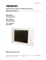
Page 1: ... R8S Page 1 22 DOC Nr B3 0038 D4 DOC High Resolution 38cm 15 LCD Monitor SCD 1597 Operating Instructions SCD 1597 R 6AV8100 1CA00 0AA0 Int ID 6GF6230 6MA SCD 1597 RT 6AV8100 1CB00 A00A Int ID 6GF6230 6MB SCD 1597 R8S 6GF6232 6MA Copyright Siemens AG ...

Page 2: ...D Monitor SCD 1597 R RT R8S Page 2 22 DOC Nr B3 0038 D4 DOC No part of this document may be reproduced or transmitted without express permission Violations will result in prosecution All rights reserved 1999 All rights reserved ...

Page 3: ...rsion SCD 1597xx T 12 3 Operation and Alignment 13 3 1 Location of the Operation and Alignment Controls 13 3 2 OSD Menu Structure 15 3 2 1 Brightness Contrast 16 3 2 2 Colour Temperature 16 3 2 3 Frequency Phase 16 3 2 4 Status 16 3 2 5 Position 16 3 2 6 Scaling 16 3 2 7 Horizontal Vertical Pan 17 3 2 8 Sharpness 18 3 2 9 Zooming 18 3 2 10 Language 18 3 2 11 Utilities 18 3 3 12 Automatic Alignment...

Page 4: ...efresh rate of 50 Hz the screen remains flicker free The SCD 1597 R RT R8S thus fulfils even the strictest ergonomic requirements Pictures of lesser resolution are expanded to fill the screen The SCD 1597 R RT R8S can simultaneously display up to 262 144 colours enabling realistic colour images and videos to be displayed The LCD monitor contains special hardware to convert a standard analogue VGA ...

Page 5: ...This chapter is mainly concerned with preparing the LCD monitor for use its installation and cabling Chapter 3 Operation All operations and adjustment possibilities for the SCD 1597 R RT R8S are described here Chapter 4 Technical Data This chapter contains technical details such as dimensions power supply environmental considerations and EMC data Important The manufacturer has gone to great length...

Page 6: ...rtake appropriate measures to minimise problems This LCD monitor is a component designed for building into industrial systems The operator of the entire plant is responsible for maintaining electromagnetic compatibility according to EMC law Repairs Before the unit is opened it must be switched off and the power supply disconnected Only authorised persons may open the unit Additions or changes to t...

Page 7: ...uthorised service technician are handling such assemblies then the following precautions should be observed When such assemblies are being handled a means of electrostatic discharge must be available This can be for example an earthed object which can be touched to discharge electrostatic voltages This applies to all tools used insulated They must also be discharged at an earthed object When assem...

Page 8: ...m and power supply Building into your system bearing in mind technical and ergonomic aspects 2 1 Removing the Packaging and Checking Individual Parts After unpacking all the delivered components they should be checked for completeness and for possible transport damage visual inspection If any deficiencies are found then please contact the service department given on the delivery note Have the deli...

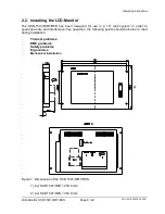
Page 9: ... designed for use in a 19 rack system In order to guarantee safe and interference free operation the following points should be borne in mind during installation Thermal problems EMC problems Safety problems Ergonomics Mechanical Installation Figure 1 Dimensions of the SCD 1597 R RT R8S 1 bei SCD 1597 R8S 279 4 mm 2 bei SCD 1597 R8S 354 8 mm 1 2 ...

Page 10: ...nts Ergonomics The screen should be easily viewable from all sides and without reflections Mechanical Installation The monitor is built into the system as a standard 19 rack component 2 2 1 Installation of AC DC power supply unit or 24V DC DC converter Either an AC DC power supply unit or a DC DC converter can be used to supply the control panel with 24VDC If an AC DC power supply unit is used it ...

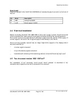
Page 11: ... to the monitor should adhere to EMC regulations A high quality 75 ohm coaxial cable must be used for the VGA signals Low quality cables can result in interference and shadowing on the display VGA Interface The VGA interface is a standard 15 pin male HD D type connector Figure 2 VGA interface Pin Signal 1 Video input RED 2 Video input GREEN 3 Video input BLUE 4 Not used 5 Not used 6 GND RED 7 GND ...

Page 12: ...y and that the screws tightened The monitor can be connected directly to the power supply note the polarity of the supply If a video signal is connected the image will appear immediately on the screen There are many possible reasons why an image might fail to appear on the display after it has been switched on no video signal connected no synchronisation signal connected horizontal and vertical sy...

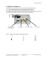
Page 13: ...cation of the Operation and Alignment Controls All controls are accessible from the front and rear of the unit They are located on the rear of the unit is shown in Figure 1 on page 31 and are used for the OSD menu Figure 3 Location of the operation and alignment elements front rear S1 UP S2 DWN S3 MEN S4 SUB S1 S2 S3 S4 Touchscreen option power supply Compartment for power supply unit VGA interfac...

Page 14: ...he menus and to select and adjust parameters The control keys are located on the rear of the monitor and have the following functions UP This key has two functions activates a sub menu function selected by the SUB key increases the value of the currently selected parameter e g brightness DWN reduces the value of the currently selected parameter e g brightness MEN Menu key calls up the OSD menu pro...

Page 15: ...dividual functions are invoked by repeatedly pressing the menu key Where sub menu points appear they can be selected by pressing the SUB menu key and activated by pressing the UP key Once a function has been selected e g brightness it can be adjusted by pressing the UP and DWN keys The individual functions and settings are described below Brightness Kontrast Colour temperature Frequency Phase Stat...

Page 16: ...llowing the desired colour temperature or colour tone to be set 3 2 3 Frequency Phase The frequency setting allows the pixel clock frequency to be adjusted This will only have to be adjusted if the automatic alignment was unable to determine the correct pixel clock frequency The phase setting allows slight picture disturbances to be eliminated 3 2 4 Status This displays the current display resolut...

Page 17: ...re to fill the entire display Fill to Aspect Ratio This setting expands the picture as much as possible while maintaining the height to width ratio of the picture Non Linear Scaling Parameters In this sub menu point the are three possible settings each for the horizontal and vertical sizes allowing the picture height and width to be adjusted independently Horiz Clipping Horizontal expansion of the...

Page 18: ...Utilities Various settings are available here to control the behaviour and testing of the monitor User Settings Six possibilities are available in this sub menu as follows OSD Horz Position Horizontal position of the OSD on the display OSD Vert Position Vertical position of the OSD on the display OSD Backround Adjust the OSD background Translucent transparent Opaque not transparent User Timeout Th...

Page 19: ...es all settings to return to the factory default values 3 3 12 Automatic Alignment Automatic alignment of the monitor is automatically activated if a picture is displayed which has never been displayed before This function can also be activated manually by pressing the key while the OSD menu is not currently being displayed A window appears which contains information on the video signal source Pre...

Page 20: ...acklight 2xCCFT Cold Cathode Fluorescent Tube Brightness typical approx 200 cd m 4 2 Power Supply Input voltage 11 4 12 6VDC Power consumption normal operation approx 18W Power consumption StandBy approx 5W 4 3 Operating Conditions Operating temperature 0 to 40 C Storage temperature 25 to 60 C Humidity max 95 non condensing 4 4 Protection Protection class Front IP65 Front screen none 4 5 Enclosure...

Page 21: ...site Sync H Frequency 30 to 100 KHz V Frequency 50 to 100 Hz 4 7 EU Declaration of Conformity on EMC Product LCD Monitor SCD 1597 R RT R8S Test foundations EU framework guidelines No 89 336 EWG No 92 031 EWG No 73 23 EWG No 93 68 EWG Harmonised standards used EN 55022 Class A A1 EN55022 A1 Edition 05 1995 Edition 08 1994 Interference emissions EN 50082 2 Edition 02 1996 Interference resistance EN ...

Page 22: ...Operating Instructions LCD Monitor SCD 1597 R RT R8S Page 22 22 DOC Nr B3 0038 D4 DOC ...

Reviews: