4 / 12
Siemens
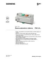
PXC3.E... Room automation stations
CM1N9203en_05
Building Technologies
2015-11-23
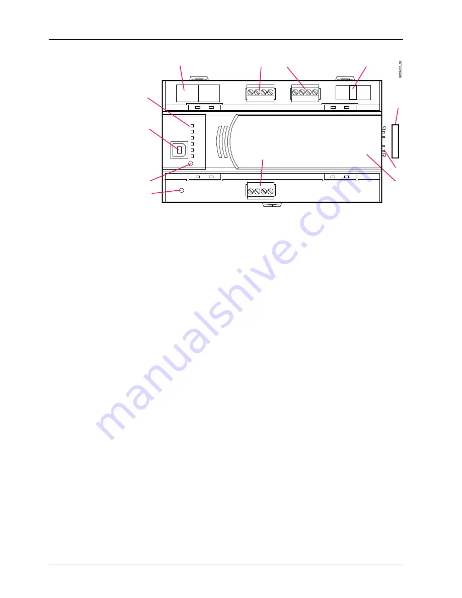
Mechanical design
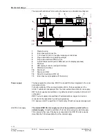
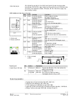
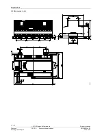
The compact build allows for mounting the devices on a standard mounting rail.
1
2
3
4
5
6
8
9
7
11
12
12
10
13
12
1
Plastic housing
2
Island bus plug connection
3
T 10 A fuse for AC 24 V peripheral supply via island bus
4
Plug-in terminal block (operating voltage)
5
Plug-in terminal block KNX PL-Link
6
2-port Ethernet switch (with 2 LEDs per port for display purposes)
7
DALI bus
8
LED display for device and system status
9
USB Device interface
10
Service pin
11
Service pin DALI
12
Slider for mounting on DIN rail
13
Island bus cover (supplied with the device)
The bus supplies for island bus, KNX PL-Link and DALI are integrated in the room
automation station.
For better reliability of the room automation station, the bus supplies and the
AC 24 V outlets are independent from the room automations station's own supply.
V6
: The bus supplies are switched on by default and can be swiched off via tool if
not needed.
V5.1
: The bus supplies are switched off automatically as long as no device is
connected to the respective bus during engineering.
V5.1 devices do NOT support the V6 functionality of field bus supply management.
The internal KNX PL-Link supply must not be operated in parallel with an
external supply
. It must be switched off via tool when using an external supply.
This is typically the case if the devices connected to the KNX PL-Link consume
more than the 160 mA available from the internal supply.
Power supply
KNX PL-Link supply

