background image

5 / 12 

Siemens 

PXC3.E...    Room automation stations 

CM1N9203en_05 

Building Technologies 


2015-11-23 

The internal bus supplies can be reinforced by external power supply modules.  

An additional TXS1.12F10 supply module must be switched on and off at the same 

time as the room automation station. Otherwise, DC 24 V island bus supply may 

sag, resulting in alarms.  


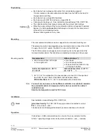
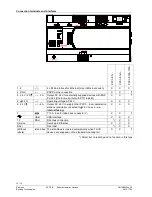
LED indicators

 (depending on the type)


920

3z

02

RUN
FLT
IB
PL
DALI
SRV

1)

2)


1) Service pin  

2) Service pin DALI 


927

0Z

05

8 7 6 5 4 3 2 1 


LED


Color


Activity


Function


RUN  Green  Continuously ON 

Continuously OFF  

Flashing 

Device ready to operate. 

No supply for device. 

Start-up or program halted 

FLT 

Red 

Continuously OFF 

Continuously ON 

Rapid flashing 

OK 

HW or SW error. 

Wrong or corrupted application. 

IB 

Yellow  Continuously ON 

Flashing 

Continuously OFF 

OK.  

Island bus communication.  

No modules connected 

TX-I/O modules not configured or 

communication fault. 

PL 

Yellow  Continuously ON 

Flashing  

Continuously OFF 

OK. 

KNX PL-Link communication.  

KNX PL-Link not used or communication 

fault. 

DALI  Yellow  Continuously ON 

Flashing  

Continuously OFF 

OK 

DALI bus communication  

DALI not used or communication fault. 

SVC   Red 

Continuously OFF 

Blinking 

Blinking per wink 

command*) 

OK. 

No application loaded. 

Physical identification of the room 

automation station. 

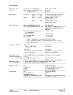
Ether-

net  

1 / 2 

Green   Continuously ON 

Continuously OFF 

Flashing 

Link active 

Link inactive 

Network activity 

Yellow  Continuously ON  

Continuously OFF 

Link 100 Mbps 

Link 10 Mbps 


*)  Wink command 

pattern: 

2s

1s

21s

5 Hz

5 Hz

9222z02

2s

1s


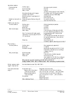
Service pins 

Pin 

Action 

Description 

(depending on the type)


1) 

Short press  Ethernet   Physical identification of the room automation 

station in the network. 


2) 

Short press  DALI test:  All ballasts On or Off. 


Long press  DALI test:  Start / stop the following function:  

"All ballasts blink (2 s On, 2 s Off)". 


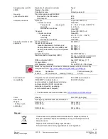
Product documentation 

  Engineering and commissioning: See ABT online help. 

  Installation manual Desigo TRA, CM111043. 

  TX-I/O planning and installation manual, CM110562.  

  Application Guide for IP Networks in Building Automation Systems, CM110668. 

  Desigo Technical principles CM110664, chapters 18 and 26. 

Island bus supply 

Summary of Contents for PXC3.E16A100A

Page 1: ...island bus to connect TX I O modules with any data point mix including bus supply Optional KNX PL Link peripheral bus to connect sensors actors and room units including bus supply Optional DALI bus to connect ballasts including bus supply Optional Connection of individual devices with KNX S Mode via KNX PL Link Ethernet switch for communication and tool connection USB Device interface Operating vo...

Page 2: ...gments 1 140 3 max 64 devices max 72 physical I O points max 64 ballasts 4 PXC3 E75 100A S55376 C132 typically 8 rooms typically 16 room segments 1 280 3 max 64 devices max 200 physical I O points PXC3 E75A 100A S55376 C133 typically 8 rooms typically 16 room segments 1 280 3 max 64 devices max 200 physical I O points max 64 ballasts 4 V5 1 V5 1SP 2 PXC3 E72 S55376 C100 typically 4 rooms typically...

Page 3: ...rcially available devices with KNX S Mode requires ETS engineering The DALI bus supports lighting control Commercially available DALI EBGs electronic ballasts can be connected Equipment combinations Depending on the type PXC3 series room automation stations can be operated with TX I O devices and devices with KNX PL Link DALI device type Description Supported 0 Fluorescent Lamps Yes 7 Switching Fu...

Page 4: ... bus supplies for island bus KNX PL Link and DALI are integrated in the room automation station For better reliability of the room automation station the bus supplies and the AC 24 V outlets are independent from the room automations station s own supply V6 The bus supplies are switched on by default and can be swiched off via tool if not needed V5 1 The bus supplies are switched off automatically ...

Page 5: ...X PL Link communication KNX PL Link not used or communication fault DALI Yellow Continuously ON Flashing Continuously OFF OK DALI bus communication DALI not used or communication fault SVC Red Continuously OFF Blinking Blinking per wink command OK No application loaded Physical identification of the room automation station Ether net 1 2 Green Continuously ON Continuously OFF Flashing Link active L...

Page 6: ...ed onto the mounting rail on the right side of the room automation station The island bus is created automatically in this process Recommended With restrictions Wall horizontal from left to right or from right to left Over head On a horizontal surface Wall vertical from bottom to top or from top to bottom Ambient temperature 5 50 C 23 122 F Ambient temperature 5 45 C 23 122 F 50 C 122 F is admissi...

Page 7: ...not used The NX PL Link supply MUST be switched off via tool if an external bus supply is used Transit power AC 24 V TX IO island bus KNX PL Link AC 24V terminals 3 4 AC 24 V 6 A terminals 7 and 8 for additional AC 24 V consumers 144 VA 6 A 48 VA 2 A 144 VA 6 A only if the sum of 10 A at terminals 5 and 6 is not exceeded Fusing of the supply outputs for field supply AC 24 V 2 A KNX PL Link termina...

Page 8: ... to 64 devices with KNX PL Link can be operated using one or two external bus supplies Protection Short circuit proof Protection against miswiring up to AC 24 V DALI interface Communications Interface type DALI galvanically separated Baud rate 1 2 kBit s Insulation strength Reinforced insulation for 230 V 1 5 kV Suitable for installations in overvoltage category III 4 kV Bus power supply Nominal v...

Page 9: ... residential commercial and industrial environments RCM conformity EMC See CM1T9222en_C1 UL approbation UL 916 EAC Eurasian conformity For all PXC3 E 100A types Meets the requirements for eu bac certification excepted PXC3 E16A 100A See product list on http www eubaccert org licences by criteria asp License Application Control accuracy K 212196 Fan Coil 4 pipe Heating Cooling 0 3 0 1 Environmental...

Page 10: ...t circuit proof with PTC resistor X X 8 24 V Operating voltage AC 24 V X X X 8 24 V 6 A Output AC 24 V to supply other PXC3 room automation stations internally connected to 24 V on pcb no internal fusing X X X F T 10 A fuse for island bus conductor V X X USB USB interface X X X 12 DALI DALI bus connection X X Service Service pin Ethernet X X X DALI DALI test X X Without labels Island bus The islan...

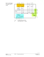
Page 11: ...en_05 Building Technologies 2015 11 23 24V CS 5 6 7 8 V 9203z05_01 T 10A 9 10 11 12 24V 24V 2A KNX 2 PTC KNX Island bus DALI DALI 3 1 2 3 4 Island Bus 1 1 2 Not with PXC3 E16A 100A 3 Only with PXC3 E A types Basic circuit diagram connections AC 24 V fusing ...

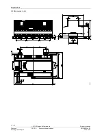
Page 12: ...12 12 Siemens PXC3 E Room automation stations CM1N9203en_05 Building Technologies 2015 11 23 Dimensions 9203M01 All dimensions in mm 2012 Siemens Switzerland Ltd Subject to change ...

Reviews: