Page 10
SmartLinx PROFIBUS DP-V1 – Operating Instructions
A5E36197302
m
m
m
m
m
Co
m
m
un
ic
at
io
n
se
tu
p
Configuring the slave device
Use the configuration software (or any equivalent master commands) to configure the
slave. Refer to the information that came with the PROFIBUS master. The Siemens device
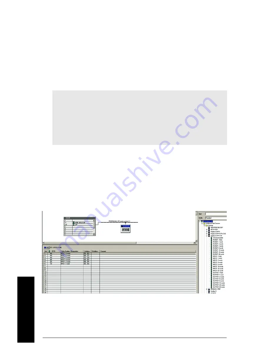
appears as a modular type slave, and should be configured as shown below.
After you import the GSD file, you can find the hardware in the hardware catalogue. If you
are using Step 7, go to PROFIBUS DP-V1 > Additional Field Devices > General > Anybus-
DPV1 IM.
The MultiRanger 200 HMI and the HydroRanger 200 HMI use 19 words of input (Read
block) of cyclic data.
Example
This example assumes that the user is familiar with Step 7 and creating a hardware
configuration.
1. Open hardware configuration from the main project window.
2. Install the PROFIBUS DP-V1 GSD file HMSB1813.gsd.
3. Assuming you have a PLC and rack setup with a PROFIBUS DP network, go to the
hardware catalog, and select the PROFIBUS DP-V1 card under <PROFIBUS
DP><Additional field devices><General><Anybus-s DPV1 IM>.
4. Drag the Anybus-s DPV1 IM device to the PROFIBUS DP network.
5. In the popup screen, set the slave address, same as you set on the rotary dials on the
PROFIBUS DP-V1 card.
Notes:
• Data is read and written with the most significant byte (MSB) first.
• The address and size of the Reads and Writes in the PLC must match the Siemens
device. If the PLC size is smaller than the Siemens size, an error will display and
only the first portion of the data will be read.
• PROFIBUS DP-V1 diagnostic bytes are not supported. However, some diagnostic
information can be accessed via reading and writing the data areas. See
Application layer on page 12
.
Summary of Contents for PROFIBUS DP-V1
Page 1: ...Operating Instructions SmartLinx PROFIBUS DP V1 08 2015 Edition Communication ...
Page 4: ...ii mmmmm Table of Contents ...
Page 30: ......
Page 31: ......


