background image

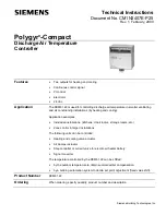
Polygyr-Compact Discharge Air Temperature Controller

Technical Instructions

Document Number CM1N3407E-P25

Rev. 1, February, 2000

Information in this publication is based on current specifications. The company reserves the right to make changes in specifications and models as
design improvements are introduced. Polygyr is a trademark of Siemens Building Technologies, Inc. © 2000 Siemens Building Technologies, Inc.

Siemens Building Technologies, Inc.
Landis & Staefa Division
1000 Deerfield Parkway
Buffalo Grove, IL  60089-4513
U.S.A.

Document No. CM1N3407E-P25
Printed in the U.S.A.

Page 5

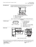
Wiring Diagrams

The following wiring diagrams only show the fundamental layout. They do not contain
the switch off functions and other switching functions which can vary from one
installation to another according to the operating conditions.


SP

SN

24V~

Y1

R M

Z1

Z3 G

Y1

G Y R M U

G0

Y2

Y2

G Y R M U

G0

N1

G0

SASC0018R1

R

R1

M


N1

RCM61.22 Discharge Air Temperature Controller

R1

FZA21.11 Remote Setting Unit

Y1

Actuator for 

 (heating)

Y2

Actuator for 

 (cooling)

Figure 3.  Exhaust Air Temperature Control with Low Limiting of Discharge Air

Temperature.

Terminal Layout

Y1

G0

Y2

Z3

Z1

M

R

G

SASC0017R1

Figure 4.  Terminal Layout.

G, G0 Operating voltage 24 Vac

G

System potential (SP)

G0 System neutral (SN)

M

Measuring neutral

R

Set point signal

Y1

Control signal 0 – 10 Vdc for 

 heating

Y2

Control signal 0 – 10 Vdc for 

 cooling

Z1

Reference  5V ± 10V

Z3

Reference  5V ± 5V

Dimensions

SASC0008R1

0.24

2.13

1.02

3.15

2.36

0.24

1.02

Pg.11

4.02

1.97

4.02

2.76

4.33

min. 1.57

max. 3.94

min. 2.76

max. 0.39

~0.91

0.75

16.73

0.08

0.79

Figure 5.  Dimensions in Inches.

Summary of Contents for Polygyr-Compact

Page 1: ...d cooling Application examples Individual installations kitchens cloak rooms storage rooms etc Zone control in larger installations The following units can be controlled Heating and cooling valve actuator Air damper actuator Step controller or current valve for electric air heater battery Signal converter The temperature controlled by the RCM61 22 can be shifted by the outdoor temperature to obtai...

Page 2: ...tes a control signal of 0 10 Vdc The outputs are switched in sequence and their mode of operation is opposed making it possible to provide sequence control of two actuators with different modes of operation Y Q Q Y Load Signal voltage Heating Cooling 0 10V SASC0016R1 0 Figure 1 Compensation The reference value is fed to the controller which shifts the set point There are two possibilities Universa...

Page 3: ...an be bent and adapted to the shape of the duct It senses the average temperature in the duct because the measuring element Ni wire extends over the total length of the flexible sensing element Unit Combinations The RCM61 22 can control various units with the following characteristics Type of control 10 Vdc Operating voltage 24 Vac Remote Setting Units The FZA21 11 remote setting unit is used for ...

Page 4: ...he supply air fan if the latte is mounted after the last air handling unit Otherwise after the air handling unit with a clearance of at least 1 64 feet The flexible sensing element should be positioned diagonally in the duct but must not come in contact with the duct wall Installation Instructions are supplied with the unit Commissioning The wiring must be checked when commissioning the installati...

Page 5: ...her switching functions which can vary from one installation to another according to the operating conditions SP SN 24V Y1 R M Z1 Z3 G Y1 G Y R M U G0 Y2 Y2 G Y R M U G0 N1 G0 SASC0018R1 R R1 M N1 RCM61 22 Discharge Air Temperature Controller R1 FZA21 11 Remote Setting Unit Y1 Actuator for heating Y2 Actuator for cooling Figure 3 Exhaust Air Temperature Control with Low Limiting of Discharge Air T...

Reviews: