


Technical Instructions
Polygyr-Compact Discharge Air Temperature Controller
Document Number CM1N3407E-P25
Rev. 1, February, 2000
Page 4
Siemens Building Technologies, Inc.
Application
When the unit is switched off or the power supply interrupted (Terminal G), the
regulating unit is automatically run to the closed or no-load position.
A transformer is required to generate the operating voltage of 24 Vac. When several
units are connected, the size of the transformer is determined by adding up the power
consumption of the individual units. See
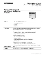
Wiring Diagrams
for connecting terminal
designations.
Every output of the RCM61.22 can control up to 10 units (actuators, converters, etc.) in
parallel operation. If a compensation input is used, attention must be paid to the input
signal.
Terminal Z1:
Input for universal compensation. The 5V ± 10V
corresponds to ± 100% of the theoretical setting range.
Terminal Z3:
Input for set point adjustment (fixed value shift). The 5V ±
5V corresponds to ± 10% of the theoretical setting range.
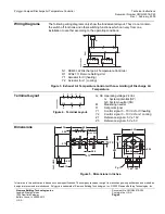
Mounting
Mounting location:
•
After the supply air fan, if the latte is mounted after the last air handling unit.
•
Otherwise, after the air handling unit, with a clearance of at least 1.64 feet.
The flexible sensing element should be positioned diagonally in the duct, but must not
come in contact with the duct wall.
Installation Instructions are supplied with the unit.
Commissioning
The wiring must be checked when commissioning the installation. To facilitate
commissioning, the controller can be operated as a P controller by using a service plug.
The correct operation of the regulating unit can be checked by setting the slider to its
limit positions. The factory-set P band Xp normally gives good control results. If
readjustment is required, the following must be noted:
•
In case of instability: Xp must be increased.
•
In case of excess stability: Xp must be decreased.
If auxiliary control functions (e.g., limitation, compensation) are fed to the controller, the
controlled value must first be adjusted, with no influence from the auxiliary control
functions. To do this, the terminals for auxiliary units must be disconnected. The
auxiliary values are adjusted only after the controlled value is adjusted.
If a remote setting unit is used, the slider for setting the desired temperature must be set
to “ext”.