Safety functions of PM330
8.2 Safety functions that can be implemented
Power Module PM330
Hardware Installation Manual, 12/2018, A5E32844552B AF
111
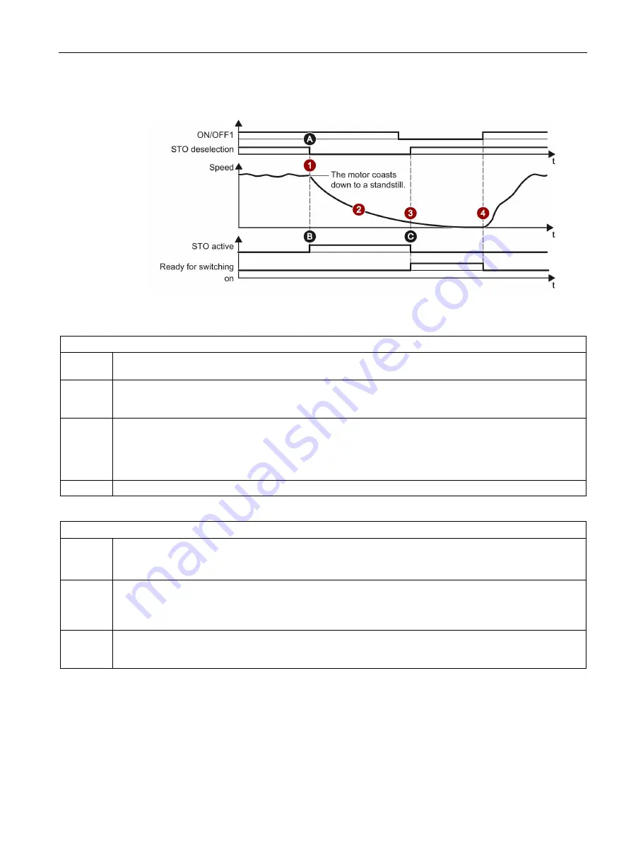
STO: Response and settings
Figure 8-2
STO: Response
Description of the response
1
STO is activated in operation. STO is activated via the two STO inputs at terminal strip X41 using the up-
stream external monitoring and control system (e.g. 3SK1).
2
After the response time, the drive immediately initiates STO. This reliably interrupts the torque-generating
energy fed to the motor. The motor coasts down to standstill, and as a result of STO, the motor is safely pre-
vented from restarting.
3
STO is deactivated by deactivating STO at the upstream external monitoring and control system (e.g. 3SK1),
and the inverter is then ready to be switched on again. To enable the switch-off signal paths using the external
monitoring and control system (e.g. 3SK1), the two feedback signal contacts of the PM330 at terminal strip
X41 must be closed.
Depending on the application, the start button may need to be pressed.
4
The inverter can be restarted with a positive signal edge at ON/OFF1.
Settings
A
STO is selected using the two STO inputs at terminal strip X41.
To be able to use the STO function, these must be enabled using the two enable switches S41 -> bring both
switches into the front position (see Chapter "Switch S41 (Page 53)").
B
The status "[44] switching on inhibited – connect 24 V to terminal STO (hardware)" is shown in parameter
r0002 and can be used for diagnostics. Using this to control specific functions, especially with regard to a
safety function, is not permissible.
In this case, directly use the monitoring and control system (e.g. 3SK1).
C
The torque-generating energy fed to the motor is safely interrupted by activating the STO function and is ena-
bled again by deactivating the STO function. In addition, the standard acknowledgment mechanism or ac-
knowledgment using the "Start" pushbutton must be performed.
Summary of Contents for PM330
Page 1: ......
Page 2: ......
Page 8: ...Table of contents Power Module PM330 6 Hardware Installation Manual 12 2018 A5E32844552B AF ...
Page 20: ...Introduction Power Module PM330 18 Hardware Installation Manual 12 2018 A5E32844552B AF ...
Page 149: ......
Page 150: ......


