background image

5

Shields

Shields for the XNET/HNET must be connected at ONE
and ONLY ONE end of the network.

Earth Ground

A good earth ground must be provided for proper tran-
sient protection of the NCC-2F and the NCC or Desigo
CC computer. Connect a separate ground to terminal 5
on the NCC-2F. See Figure 4, 5 or 6 as applicable.

Ground Fault Detection

The NCC-2F provides electrical isolation between the
NCC or Desigo CC computer and the XNET. This al-
lows for ground fault detection to be enabled on the
XNET. Ground fault detection is only possible if ALL
NCC or Desigo CC computers in the system are con-
nected to XNET with an NCC-2F (or NCC-1Fs for exist-
ing NCC systems).

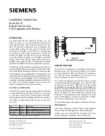
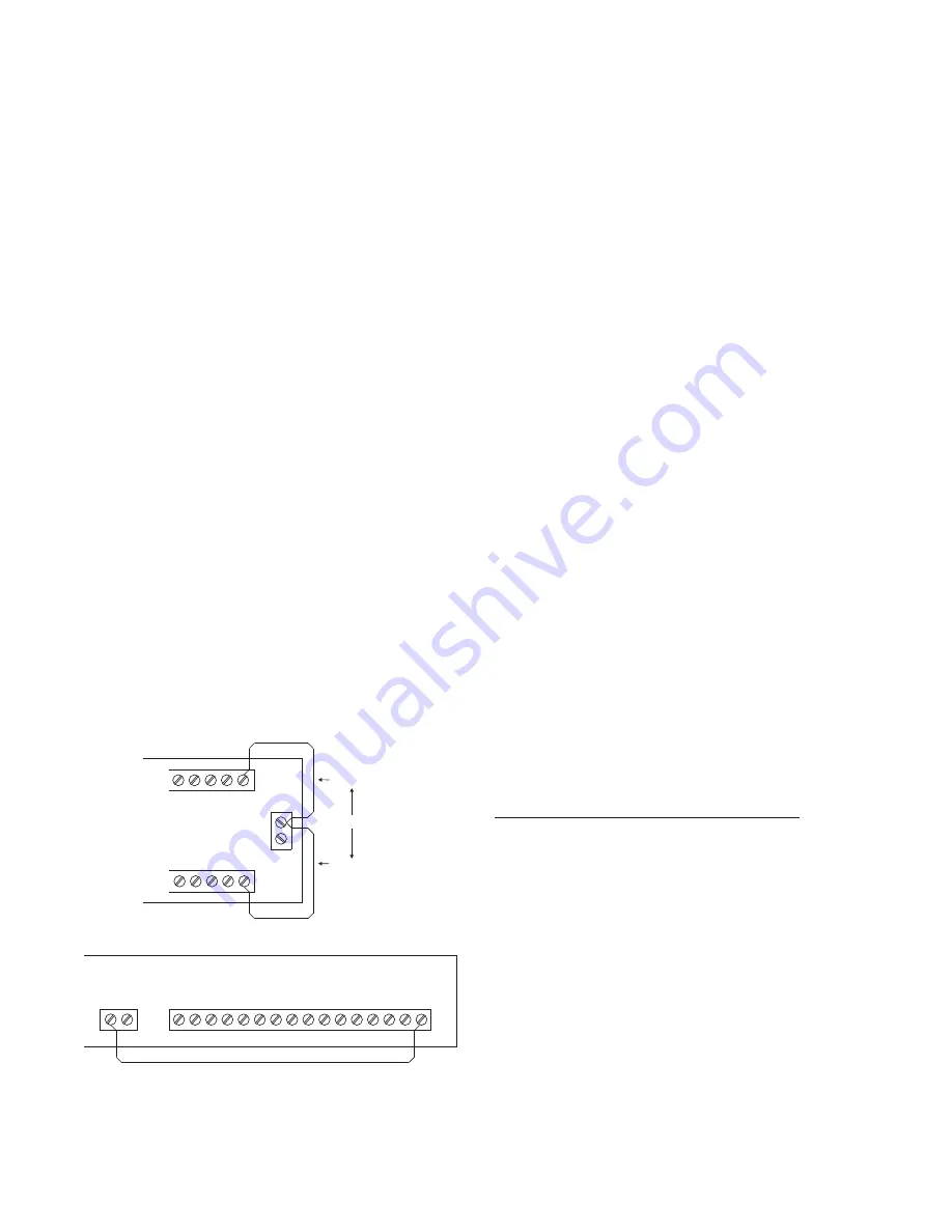
Ground fault detection must be enabled at a
NIM-1R/-1W or NIC-C. Select one and only one NIM-1R/
-1W or NIC-C in the system where the ground fault is to
be detected. You must locate the NIM-1R/-1W in a cabi-
net with either an MMB, SMB or a PSR-1. See Figure 7
for the wiring diagram.

If the XNET is divided into multiple sections of copper
wire using fiber optic segments, ground fault detection
can be enabled at one NIM-1R/-1W or NIC-C for each
section of copper wire. Refer to the NIC-C Installation
Instructions, P/N 315-033240 if you wish to use the
NIC-C to provide ground fault detection.

For ground fault detection on HNET systems,


refer to

the NIC-C Installation Instructions, P/N 315-033240.

DRIVER INSTALLATION

The products which utilize the NCC-2F cards run on
MicroSoft Windows NT, XP and Windows7 operating
systems (OS). The Windows OS type used must be in
accordance with the product to be used (i.e. NCC or
Desigo CC). The drivers are distributed with the instal-
lation disks for the product software.

In the following procedures, there is a reference to a
“driver folder”. For both types of installation disks, use
the folder with the Oxford UART drivers. The exact (drive)
path for this folder is identified in the steps below, and
the drive letter that begins the path should reflect the
designation for the CD/DVD drive being used for software
installation.

When a PC with an NCC-2F card is first started, the card
is detected by Windows. Depending on the Windows
operating system type, a different user-interaction is
required to install the drivers.

Windows XP (NCC)

Driver folder:
D:\drivers\NCC2F_DRIVERS\OXUART_v512_Drivers

Load the disk in the CD-ROM drive, and use the following
instructions for installing the drivers. For each NCC-2F
card in the computer, Windows automatically prompts
the user for drivers. There are three drivers to install: one
for the PCI card UART and two for the PCI communi-
cation ports. You will repeat the outlined installation
steps a total of three times.

If two NCC-2F cards are physically installed: After the
first card is installed, the presence of the second NCC-2F
card will cause Windows to prompt the user for the drivers.
For the second NCC-2F card, follow the same steps as
practiced for the driver installation of the first NCC-2F card.

When all is complete, refer to the Device Manager to
check the COM port designations, and view any instal-
lation issues.

The following steps take you through the process:

1. When the NCC-2F is first installed, Windows detects
the new hardware. Refer to Figure 8.

At this point select the “No, not this time” option and
click on Next>.

TB3

NIM-1R/-1W

IN TB4

NIM-1R/-1W

IN TB3

USE ONLY ONE

TB5

TB4

MOM-2

MOM-4

TB7

TB4

13

14

15

16

9

10

11

12

13

14

15

16

12

13

14

15

16

12

5

6

7

8

+

1

1

2

2

3

4

_

+

1

2

_

Figure 7

Wiring for Ground Fault Detection (XNET)

Summary of Contents for NCC-2F

Page 1: ... D K O T S O H n e e r G t i m s n a r t o t a t a d e t a c i d n i o t s k n i l B 4 S D A H C w o l l e Y t c e l e s A l e n n a h C l a u d i v i d n i e t a c i d n i o t s k n i l B 5 S D B H C w o l l e Y t c e l e s B l e n n a h C l a u d i v i d n i e t a c i d n i o t s k n i l B l e n n a h c t a h t n o t l u a f 7 e l y t S a s e t a c i d n i y d a e t s s i D E L f I Installation ...

Page 2: ...he NCC or Desigo CC XNET and HNET port as signment can be changed to agree with any port assign ment at the time of install or update Either board can handle XNET and either board can handle HNET There is no difference in the boards However XNET and HNET are different protocols so HNET wiring should go to the board with the COM port assigned to HNET and likewise XNET wiring should go to the board ...

Page 3: ...ry pairs See Figure 6 for wiring details 1 2 3 4 5 6 7 8 9 10 11 12 13 14 15 16 17 18 19 20 21 22 23 24 SEE NOTE 7 MUST BE IN SAME ENCLOSURE AS THE PMI DO NOT USE DO NOT USE DO NOT USE DO NOT USE ONE SLOT OF CC 5 NIC C 1 2 3 4 5 PAIR A SUPERVISED POWER LIMITED PAIR B OMIT FOR STYLE 4 SUPERVISED POWER LIMITED LOCATED INSIDE NCC DESIGO CC VNT NOTE IF THE NCC DESIGO CC VNT IS LOCATED AT THE END OF TH...

Page 4: ... twisted pair 25μF max line to line Shielded twisted pair 15μF max line to line 2μF max line to shield 3 Use twisted pair or twisted shielded pair 4 Terminate shields at one and only one NIC C 5 Power limited to NFPA 70 per NEC 760 6 Maximum voltage 8V P P 7 Maximum current 75mA during message transmission 8 Each pair independently supervised 9 Positive or negative ground fault detected at 10K ohm...

Page 5: ... disks for the product software In the following procedures there is a reference to a driver folder For both types of installation disks use the folder with the Oxford UART drivers The exact drive path for this folder is identified in the steps below and the drive letter that begins the path should reflect the designation for the CD DVD drive being used for software installation When a PC with an ...

Page 6: ...ted exercised via the Browse button Refer to Figure 10 Figure 10 Choosing Search and Installation Options 4 After you highlight the folder when in Browse click OK to proceed Now that the path is set click Next Windows XP will install the appropriate drivers When you see the following Hardware Installation warning click Continue Anyway Refer to Figure 11 Figure 11 Hardware Installation Warning 5 Th...

Page 7: ...s XP will use the first available COM port for communication Figure 14 Install From A List Or Specific Location 8 Select Next and search for the folder where the OXUART_v512_DRIVERS are located Refer to Figure 15 Figure 15 Choosing Search and Installation Options 9 After you highlight the folder click OK to proceed Now that the path is set click Next Windows XP then installs the appropriate driver...

Page 8: ...gure 18 Install From A List Or Specific Location 12 Select Next and search for the CD ROM drive where the OXUART_v512_DRIVERS folder is located 13 After you highlight the folder click OK to proceed Now that the path is set click Next Windows XP will install the appropriate drivers When you see the fol lowing Hardware Installation warning click Continue Anyway Refer to Figure 19 Figure 19 Software ...

Page 9: ...owing instructions for installing the drivers When all is complete refer to the Device Manager to check the COM port designations and view any instal lation issues The following steps take you through the process 1 When the NCC 2F card is first installed Windows 7 detects the new hardware To verify the detected hard ware access the Device Manager as described in the CONFIGURATION section or equiva...

Page 10: ...r based on the selected folder After a driver install one of two screens as shown in Figures 24 or 25 displays Figure 24 Successful Driver Installation Notes 1 The screen above reflects a good install where the correct PCI Serial Port entry was selected from the Device Manager s entry under Other Devices 2 The screen below reflects an incorrect Device Manager PCI Serial Port entry is selected i e ...

Page 11: ...Add a separate CC 2 or CC 5 card cage to one node on the XLS network system Connect this cage to the XLS network system node using a 60 pin ribbon cable BCL At the added CC 2 or CC 5 card cage add and secure into connector P1 an Interface Isolation Card IIC Refer to Installation Instructions P N 315 050328 Plug the other end of the 60 pin cable into the male ribbon cable receptacle on the IIC Inse...

Page 12: ...n i r u d x a m A m 5 7 1 NCC 2F 4 3 5 B1 A1 B2 A2 1 2 3 4 5 6 7 8 1 2 3 4 5 6 7 8 9 10 11 12 13 14 15 16 9 10 11 12 13 14 15 16 ONE SLOT OF CC 5 ONE SLOT OF CC 5 NIC C NRC PAIR A SUPERVISED POWER LIMITED PAIR B SUPERVISED POWER LIMITED FROM NRC IN LOCAL XLS TO NEXT NRC 2 Figure 28 NRC XNET To NCC 2F Connections NOTES 1 For this configuration only one NCC 2F card can be connected to the NIC C card...

Reviews: