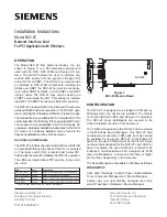
1 1
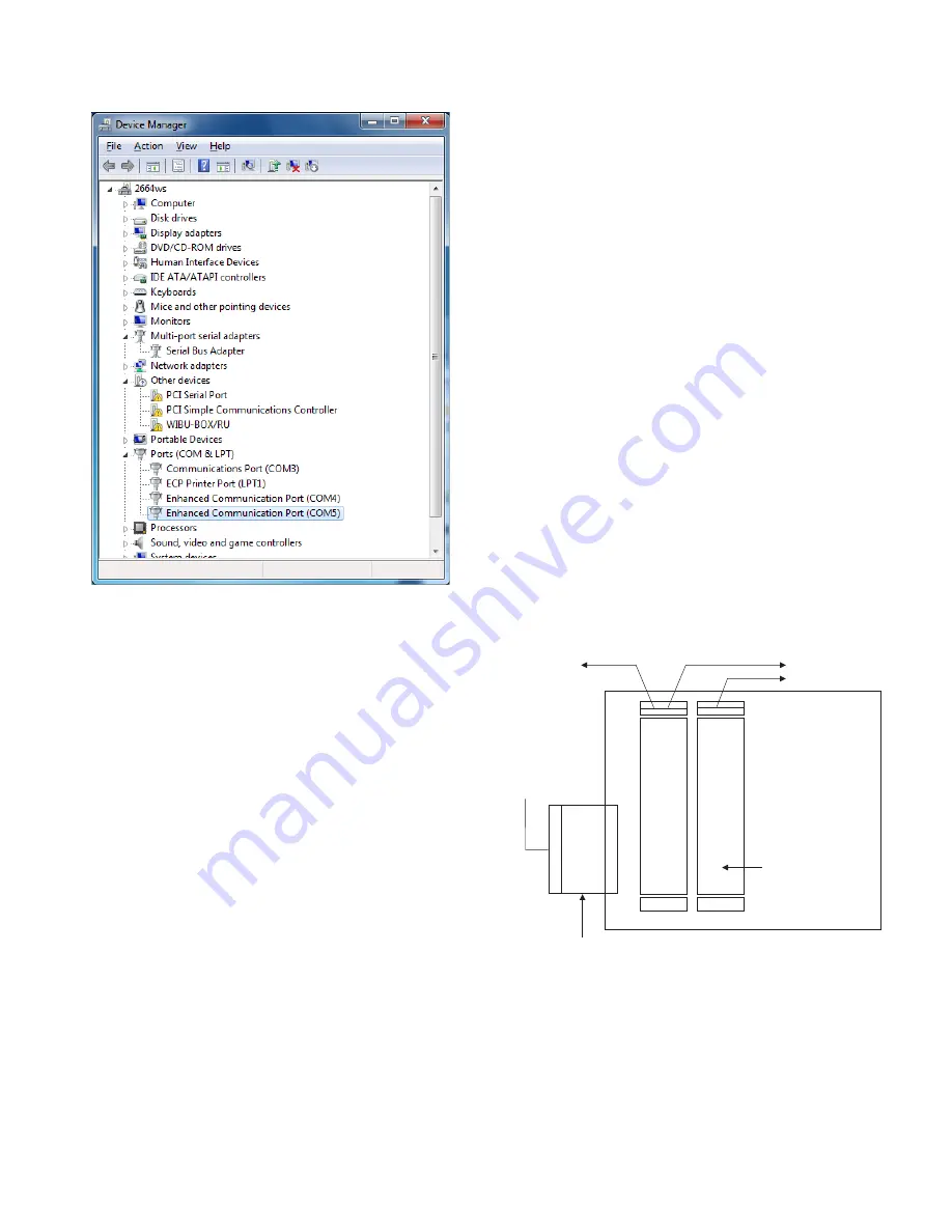
Figure 26
Verify Device Manager Entries
Notes:
1. A “Multi-port serial adapters” entry now appears, which
shows a “Serial Bus Adapter” entry (can be accessed by
clicking on the arrow symbol to the left of the entry)
represents the NCC-2F hardware.
2. The “Ports (COM & LPT)” entry now shows (when
expanded) the COM ports associated with the two NCC-
2F card ports, Enhanced Communication Port (COM4
and COM5).
3. Under Other Devices, other detected hardware not
handled by this install may still appear (as shown above,
including a non-NCC-2F PCI Serial Port).
The driver installation procedure should now be complete
and any installation media in the CD/DVD-ROM drive
can be removed.
NRC BASED XNET CONNECTION
When an NCC or Desigo CC connects to a NRC-based
XNET network of FireFinder-XLS products, the NCC-
2F card requires additional interface hardware. In such
an installation, the NCC-2F card connects to a NIC-C
module – which in turn is connected to a dedicated
NRC module.
Connect an NCC or Desigo CC to an XLS network system
(rev. PMI07.00 or higher) using NRC network cards in-
stead of a NIC-C as described in the following information.
Add a separate CC-2 or CC-5 card cage to one node on
the XLS network system.
Connect this cage to the XLS network system node using
a 60 pin ribbon cable (BCL). At the added CC-2 or CC-5
card cage, add and secure into connector P1 an Interface
Isolation Card (IIC). (Refer to Installation Instructions, P/N
315-050328.) Plug the other end of the 60 pin cable into
the male ribbon cable receptacle on the IIC.
Insert another NRC and a NIC-C into this isolated card
cage. Do not enter these cards into the Zeus configura-
tion for this node or for the network system. Only the
NCC or Desigo CC is added to the Zeus configuration
as a network node. Note that this NRC is another (sec-
ond NRC) card required for communicating with the
NCC or Desigo CC.
Wire the NRC so that it is inserted into the XLS network
ring. Refer to Figures 27 and 28 as well as the NRC In-
stallation Instructions, P/N 315-050337. Connect the
NCC-2F to the NIC-C as shown in Figure 28. Connect
Pair A for Style 4 and Pairs A and B for Style 7. Address
the NIC-C at address 003.
NRC
CC-2/CC-5
IIC
NIC-C
TO NEXT NRC
FROM PREVIOUS NRC
60 PIN CABLE
FROM PREVIOUS
XLS CARD CAGE
NIC ADDRESS
NOT USED
SET AT 003
INTERFACE ISOLATION CARD
(ISOLATES CARD CAGE SO ONLY
POWER IS USED FROM LOCAL NODE)
TO NCC/DESIGO CC STYLE 4/7
Figure 27
NRC To NCC/Desigo CC Card Cage Connections


