background image

Operating the Control Panel 


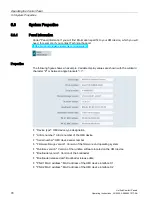
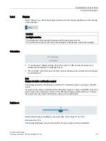
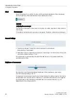
5.5 Network and Internet 


Unified Comfort Panels 

92


Operating Instructions, 03/2020, A5E46641217-AA 

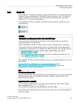
Sm@rtServer 


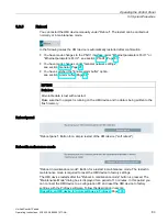
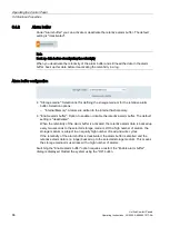
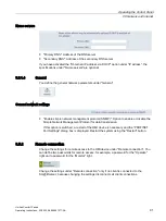
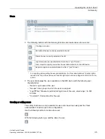
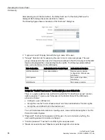
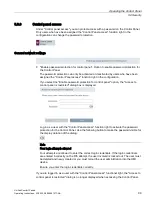
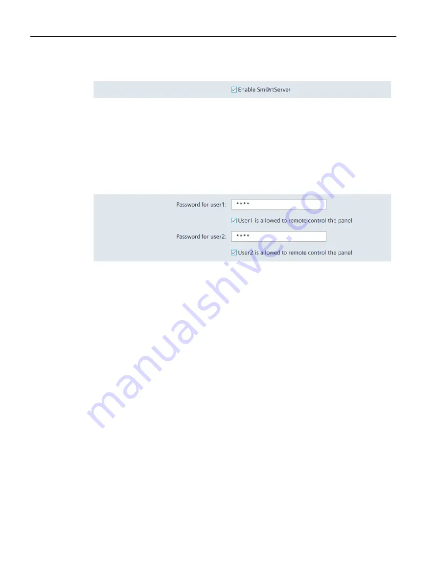
"Enable Sm@rtServer": Option to enable or disable the Sm@rtServer on the HMI device. 

The default setting is "deactivated". 
If the Sm@rtServer is started on an HMI device, you can access the HMI device via a 

suitable client. Suitable clients are, for example, Tigervnc or the Sm@rtClient application. 

Depending on the settings under "Users", a user logged in via a client can operate or monitor 

the HMI device. 

Users 


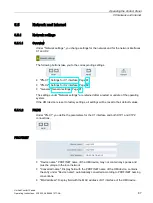
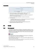
In this area you define which rights are associated with which password. Several users can 

access the Sm@rtServer simultaneously via a password. If no password is specified, then 

users with the appropriate authorization can log in without a password. 


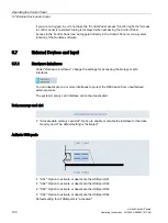
"Password for user 1": First password for access to the HMI device. Default setting: "No 

password". 


"User 1 is allowed to remote control the panel": Option to activate the "Operate" right 

for a user who logs in with password 1. The default setting is "deactivated". 


"Password for user 2": Second password for access to the HMI device. Default setting: 

"No password". 


"User 2 is allowed to remote control the panel": Option to activate the "Operate" right 

for a user who logs in with password 2. The default setting is "deactivated". 

Summary of Contents for MTP1000 Unified Comfort

Page 1: ...ns 03 2020 A5E46641217 AA Preface Overview 1 Safety instructions 2 Mounting and connecting the device 3 Operating the device 4 Operating the Control Panel 5 Transferring data 6 Device maintenance and repair 7 Technical information 8 Technical Support A Markings and symbols B Abbreviations C ...

Page 2: ...onnel qualified for the specific task in accordance with the relevant documentation in particular its warning notices and safety instructions Qualified personnel are those who based on their training and experience are capable of identifying risks and avoiding potential hazards when working with these products systems Proper use of Siemens products Note the following WARNING Siemens products may o...

Page 3: ...y and process communication is needed to understand the operating instructions Knowledge of personal computers and Microsoft operating systems is required Scope of the operating instructions The operating instructions apply to the following HMI devices in conjunction with the SIMATIC WinCC Unified software Name Type Article number device with Siemens logo Article number device with out Siemens log...

Page 4: ...e symbol are registered trademarks of Siemens AG HMI SIMATIC WinCC Style conventions Style Convention Scope Add screen Terminology that appears in the user interface for example dialog box names tabs buttons menu commands Required input for example limit values tag values Path information File Edit Operational sequences for example menu commands shortcut menu commands F1 Alt P Keyboard operation P...

Page 5: ...TP2200 Unified Comfort WinCC SIMATIC WinCC Unified V16 or higher Instead of the full product name the short product name is also used without the suffix Unified Comfort for example MTP700 representative for MTP700 Unified Comfort Figures This manual contains figures of the described devices The figures can deviate from the delivered device in detail Picture components are marked with black positio...

Page 6: ...Preface Unified Comfort Panels 6 Operating Instructions 03 2020 A5E46641217 AA ...

Page 7: ... 3 1 2 Checking the operating conditions 29 3 1 3 Permitted mounting positions 30 3 1 4 Checking clearances 32 3 1 5 Preparing the mounting cutout 33 3 2 Mounting the device 34 3 2 1 Notes on installation 34 3 2 2 Positions of the mounting clips 35 3 2 3 Fastening the built in device with mounting clips 37 3 3 Installing a strain relief 38 3 4 Connecting the device 40 3 4 1 Notes on connection 40 ...

Page 8: ...concept 69 4 7 2 Changing the memory card 72 5 Operating the Control Panel 75 5 1 Opening the settings 75 5 2 Overview of functions 77 5 3 System Properties 78 5 3 1 Panel information 78 5 3 2 Display 79 5 3 3 Screensaver 80 5 3 4 Update OS 81 5 3 5 Reboot 83 5 3 6 Performance 84 5 4 Runtime Properties 85 5 4 1 Automatic runtime start 85 5 4 2 Alarm buffer 86 5 5 Network and Internet 87 5 5 1 Netw...

Page 9: ...g the operating system via WinCC 132 6 7 3 Resetting an HMI device to factory settings via ProSave 133 7 Device maintenance and repair 135 7 1 General information on maintenance and servicing 135 7 2 Clean the glass front of the HMI device 135 7 3 Using the maintenance mode 136 7 4 Spare parts and repairs 138 7 5 Recycling and disposal 138 8 Technical information 139 8 1 Software license agreement...

Page 10: ...ied Comfort 155 8 8 Technical specifications 156 8 8 1 MTP700 MTP1000 MTP1200 Unified Comfort 156 8 8 2 MTP1500 MTP1900 MTP2200 Unified Comfort 158 8 9 Description of the interfaces 160 8 9 1 DC24V X80 160 8 9 2 RS422 485 X20 160 8 9 3 PROFINET LAN X1 161 8 9 4 PROFINET LAN X2 161 8 9 5 USB X61 X62 X63 X64 162 8 10 Communication with controllers 162 8 11 Scope of functions with WinCC 163 A Technic...

Page 11: ...egibility as well as more brilliant colors and high contrast of the display combined with significantly higher ruggedness of the multi touch technology Integrated functionality for all device sizes from 7 to 22 Increased hardware performance as well as higher system limits for significantly larger applications based on a panel based system than before High level of IT security to protect the syste...

Page 12: ... from 10 to 100 Operation Capacitive multi touch screen Software Web browser for displaying Internet pages Viewer for PDF documents Editor for Word and Excel documents and other formats File manager Media Player Runtime software with logging and scripting functionality system diagnostics for SIMATIC controllers display of trends f x f t etc Data storage Two slots for memory cards One data memory c...

Page 13: ...des the following components Name Figure Quantity HMI device 1 Installation instructions Quick Install Guide 1 Power supply connector 1 Mounting clips steel captive 8 MTP700 12 MTP1000 MTP1200 MTP1500 MTP1900 MTP2200 Strain relief element Strain relief 1 MTP700 MTP1000 MTP1200 Plastic strain relief element 3 MTP700 MTP1000 MTP1200 Strain relief 1 MTP1500 MTP1900 MTP2200 ...

Page 14: ... Panels using the MTP1900 Unified Comfort with Siemens logo as an example The remaining Unified Comfort Panels differ in the size of the front the interfaces are identical for all Unified Comfort Panels Front view and side view Display and capacitive multi touch screen Recesses for mounting clips Mounting seal Bottom view Interfaces detailed description Page 15 Recesses for mounting clips ...

Page 15: ...faces The figure below shows the interfaces of the Unified Comfort Panels using the interface plate of the devices with display diagonal 15 as an example X80 power supply connector X1 PROFINET LAN 10 100 Mbit Connection for equipotential bonding functional grounding X61 USB X20 RS422 485 SUB D X62 USB X2 PROFINET LAN 10 100 1000 Mb X63 USB Maintenance button X64 USB For devices with display diagon...

Page 16: ...ket adapter for RS422 RS485 interface 6AV6671 8XD00 Plug for the power supply of the HMI device 2 pin screw technology 6AV6671 8XA00 stands for the variant key of the article number Protective films Name Article number 7 front protective film for MTP700 Unified Comfort 6AV6881 0GJ22 10 front protective film for MTP1000 Unified Comfort 6AV6881 0KJ22 12 front protective film for MTP1200 Unified Comf...

Page 17: ...h pen system for resistive and capacitive touch systems 6AV2181 8AV20 stands for the variant key of the article number Additional USB accessories Additional USB accessories can be found on the Internet in the following entry FAQ 19188460 https support industry siemens com cs ww en view 19188460 Other accessories You can find additional accessories for SIMATIC HMI devices on the Internet at the fol...

Page 18: ...t Configuration During the configuration phase you create the user interfaces for operating and monitoring of the technical process on a configuration PC with WinCC Project design comprises Creating project data Saving project data Testing project data Simulating project data Transfer After compiling the configuration you download the project to the HMI device Process management Process management...

Page 19: ...r e mail accounts receive e mails send e mails and import mail files from other applications File Browser With the File Browser you can display and manage files on the HMI device Media Player You can use the Media Player to play audio and video files PDF Viewer You can use the PDF Viewer to view PDF documents Printer Configuration You can display and manage pre installed printers with the Printer ...

Page 20: ...Overview 1 7 Apps and software options Unified Comfort Panels 20 Operating Instructions 03 2020 A5E46641217 AA ...

Page 21: ...ly be possible by means of a key or tool and only for qualified personnel Electrocution risk when control cabinet is open When you open the control cabinet there may be a dangerous voltage at certain areas or components Touching these areas or components can cause electrocution Disconnect the cabinet from the mains before opening it Do not plug in or pull out plant components during operation The ...

Page 22: ...to protect plants systems machines and networks against cyber threats it is necessary to implement and continuously maintain a holistic state of the art industrial security concept Siemens products and solutions constitute one element of such a concept Customers are responsible for preventing unauthorized access to their plants systems machines and networks Such systems machines and components sho...

Page 23: ...re passwords and a standard user account for normal operation Other measures such as the use of security policies should be applied as needed 2 2 Security management for HMI devices Data security Data from external sources The HMI device has external interfaces and can be connected to the Internet Edge management allows you to install apps from any source Data from untrusted sources represents a s...

Page 24: ... or if the user saves personal information on the same medium e g hard disk and therefore creates a personal reference in the process the user has to ensure meeting the guidelines regarding data protection 2 4 Notes about usage NOTICE The HMI device is approved for indoor use only The HMI device may be damaged if it is operated outdoors Operate the HMI device indoors only Note Operate the device o...

Page 25: ...erence are observed Suitable measures for achieving these limits for use in a mixed use zone include Installation of the HMI device in grounded control cabinets Use of filters in electrical supply lines Individual acceptance is required Use in residential areas Note HMI device not intended for use in residential area The HMI device is not intended for use in residential areas Operation of an HMI d...

Page 26: ...extreme cases the image is permanently displayed The image outline usually disappears on its own when the screen remains switched off for some time Screensavers that use active black when the backlight is on reduce the burn in effect Activate the screensaver Page 80 Backlight The brightness of the backlight decreases incrementally during operational life You can extend the service life of the disp...

Page 27: ...lug or pull connectors in potentially explosive atmospheres When you plug or pull the plug in connector during operation there is a risk of a flashover A flashover can cause an explosion in a hazardous area resulting in death or severe injuries Plugging or pulling of plug in connectors for example of a 24 V DC power supply connector or even of a memory card is prohibited in a hazardous area Do not...

Page 28: ...Safety instructions 2 5 Use in hazardous areas Unified Comfort Panels 28 Operating Instructions 03 2020 A5E46641217 AA ...

Page 29: ...he HMI device You must pass along the enclosed documentation to any subsequent owner or user of the HMI device Make sure that every supplement to the documentation that you receive is stored together with the operating instructions 3 1 2 Checking the operating conditions Observe the following aspects before installing the HMI device 1 Familiarize yourself with the standards approvals EMC parameter...

Page 30: ...he maximum permitted ambient temperature for operation If there is sufficient convection from forced ventilation the HMI device can also be operated in the inclined mounting position up to the maximum permitted ambient temperature for vertical mounting The HMI device may otherwise be damaged and its certifications and warranty will be void The working temperature ranges listed in this section appl...

Page 31: ...6641217 AA 31 Mounting in landscape format All Unified Comfort HMI devices are suitable for installation in landscape format Mounting in portrait format All Unified Comfort HMI devices are suitable for installation in portrait format Select the appropriate screen format during configuration See also Climate diagram Page 149 ...

Page 32: ...t 50 mm above and 50 mm below the mounting cutout in the y direction for ventilation At least 10 mm behind the rear panel of the HMI device in the z direction The following figure shows the clearances for mounting the HMI devices in landscape format and portrait format using MTP1900 Unified Comfort as an example Clearance for mounting in landscape format Clearance for mounting in portrait format x...

Page 33: ...d deviation from plane at the mounting cutout 0 5 mm This condition must be met for the mounted HMI device Permissible surface roughness in the area of the seal 120 µm Rz 120 Compatibility of the mounting cutout to other HMI devices The Unified Comfort HMI devices are mounting compatible with standard SIMATIC Industrial PCs Industrial Flat Panels and Industrial Thin Clients with identical display ...

Page 34: ... according to IEC 61010 2 201 for use in industrial control equipment For approval and operation according to IEC 61010 2 201 the device must be installed in an enclosure or integrated in a cabinet The enclosure or the cabinet must provide protection against electric shock and the spread of fire The enclosure or the cabinet must meet the requirements for mechanical strength and the degree of prote...

Page 35: ...s with the mounting clips from the accessory pack which are also available as accessories Page 16 For the 7 device MTP700 Unified Comfort you need 7 mounting clips for all other devices 12 mounting clips To achieve degree of protection IP65 for the respective device the mounting clips must be installed at the positions shown below Device Positions of the mounting clips 7 device 10 device 12 device...

Page 36: ...Mounting and connecting the device 3 2 Mounting the device Unified Comfort Panels 36 Operating Instructions 03 2020 A5E46641217 AA Device Positions of the mounting clips 15 devices 19 devices 22 devices ...

Page 37: ...the device The following material and tools are available The mounting clips from the accessory kit One torque screwdriver with cross tip insert size 2 Procedure Note If the mounting seal is damaged the degree of protection is not guaranteed 1 Insert the device into the mounting cutout from the front 2 Make sure that all four spring locks on the top and bottom of the device fully engage If necessa...

Page 38: ... Installing a strain relief The device s scope of delivery includes a strain relief plate with the required number of fixing screws Note If the strain relief plate of devices with display diagonal 12 is mounted then the strain relief plate projects beyond the outer dimensions of the device Screw on the strain relief plate of the devices with display diagonal 12 only after the device has been insta...

Page 39: ...ate to the device with a torque of 0 8 Nm using the two screws supplied The figure below shows the installation using the MTP700 Unified Comfort HMI device as an example HMI devices with display diagonal 15 Fasten the strain relief plate to the device with a torque of 0 8 Nm using the two screws supplied The figure below shows the installation using the MTP1900 Unified Comfort HMI device as an exa...

Page 40: ...24 V DC power supply cables on the 24 V DC power supply connector Use only shielded standard cables as data connecting cables order information is available in the Industry Mall https mall industry siemens com Connection sequence NOTICE Damage to the HMI device If you do not keep to the connection sequence you could damage the HMI device It is crucial that you connect the HMI device in the followi...

Page 41: ...ration When connecting the cables make sure that you do not bend the contact pins Secure the cable connectors by fastening the connector to the socket with screws Provide adequate strain relief for all connecting cables The pin assignment of the ports is described in the technical specifications 3 4 2 Connecting the equipotential bonding circuit Differences in electrical potential Differences in e...

Page 42: ...equipotential bonding conductor must be capable of handling the maximum equalizing current Equipotential bonding cables are required between two control cabinets with a minimum conductor cross section of 16 mm Use equipotential bonding conductors made of copper or galvanized steel Establish a large surface contact between the equipotential bonding conductors and the grounding protective conductor ...

Page 43: ...ial bonding using the MTP1900 Unified Comfort as an example and similarly applies to the other Unified Comfort HMI devices Control cabinet Equipotential bonding cable 4 mm 2 Equipotential busbar for equipotential bonding cables grounding connection and shield support of the data cables PROFINET data cable Shield of the PROFINET data cable connected to the equipotential busbar Cable clip Ground bar...

Page 44: ...llowing applies for a non isolated system design Connect the GND 24 V connection from the 24 V power supply output to equipotential bonding for uniform reference potential You should always select a central point of termination NOTICE External protective circuit An external protective circuit is required for operation with 24 V DC see section 7 Lightning protection and overvoltage protection in fu...

Page 45: ... from the screwdriver could damage the HMI device socket Connect the power supply cables when the power supply connector is unplugged from the HMI device 1 Switch off the power supply 2 Connect the power supply cables to the power supply connector as shown in the above figure 3 Connect the power supply connector to the corresponding socket of the HMI device as shown in the above figure Check the c...

Page 46: ...how to connect the HMI device to a configuration PC with a Unified Comfort Panel with display diagonal 15 as an example Procedure Proceed as follows 1 Switch off the HMI device 2 Switch on the configuration PC 3 Connect the HMI device to the configuration PC via the X1 or X2 interface Note The technology on which the X2 is based allows a higher data transfer rate than the X1 interface 4 Switch on ...

Page 47: ... only update the operating system by restoring the factory settings via one of the two PROFINET LAN interfaces Connecting multiple HMI devices in succession If you connect more than one HMI device with the same IP address in succession to a single configuration PC you need to ping the configuration PC once from the HMI device on each changeover of the HMI device 3 4 5 Connecting the controller Wir...

Page 48: ...ATIC S7 controller you may experience malfunctions Use only approved cables to connect a SIMATIC S7 controller Use only straight connectors Use only straight cables whenever possible to connect a controller Bent connectors can cover adjacent interfaces Standard cables are available for the connection You can find order information in the Industry Mall https mall industry siemens com PROFINET Note ...

Page 49: ...ou connect an external device with a 230 V power supply to the USB port in a plant that is electrically isolated you might experience functional problems Use a non isolated plant installation Excessive rated load of the USB interface A USB device with too high a power load may possibly cause functional problems Observe the values for the maximum load rating of the USB interface see section Technic...

Page 50: ... sticks The following file systems are supported for USB sticks NTFS FAT32 We recommend using the NTFS formatting method which offers greater data consistency and flexibility regarding the size of the saved files Connection diagram The following figure shows the example of a Unified Comfort Panel with a screen diagonal 15 as you connect a USB device ...

Page 51: ...gonal 15 as an example Note when connecting Note Cables for data exchange If you use cables without a metallic netting shield between the HMI device and printer you may experience functional problems Use cables with metal braided shielding grounded at both ends only for connecting the HMI device and the printer Note Some printers may require that you also set the ASCII character set used in the pr...

Page 52: ...cal web page CUPS Common Unix Printing System under localhost 631 To open the printer administration proceed as follows 1 Open the printer administration in the Control Panel under Apps Printer Configuration Start 2 Select Printers The Printers page shows the pre installed printers To change the settings of a printer delete the printer or display the print jobs click on the printer name in the Que...

Page 53: ...may have crossed the cables on the power supply connector Check the connected cables and correct the polarity if necessary If a project is available on the HMI device then the project is started after the defined delay time If there is no project on the HMI device the Control Panel is displayed 2 If desired operate the project or configure the HMI device via the Control Panel If you no longer need...

Page 54: ...he strain relief plate is mounted see section Installing a strain relief Page 38 HMI devices with display diagonal 12 For devices with 12 display diagonal secure the cables to the strain relief plate and to the plastic strain relief elements supplied The following figures use the MTP700 Unified Comfort as an example to show how to install the plastic strain relief elements Next use cable ties to s...

Page 55: ...hat the connectors must be secured in a captive manner at the interfaces WARNING Explosion hazard from sparks when connectors come loose If a plug connector comes loose from the associated device interface during operation in a hazardous area a spark over at the interface may cause an explosion Death or serious physical injury as well as property damage may result For use in hazardous areas it mus...

Page 56: ...nel is displayed 2 Switch off power to the HMI device 3 When you use the HMI device in a hazardous area make sure that one of the two following requirements is met The area is no longer hazardous or the device and its plug in connections are de energized 4 Remove all cable ties on the HMI device used for strain relief 5 Remove all plug in connectors and the equipotential bonding cable from the HMI...

Page 57: ...dustrial grade are approved only for the commissioning 4 2 Important notes on touch screen You operate the capacitive multi touch screen with one finger or with two finger gestures WARNING Personal injury or property damage due to no earth connection An inadequate ground connection or the lack of one will cause malfunction of the capacitive multi touch screen Functions may not work properly This c...

Page 58: ... touch the touch screen with a finger or a touch pen WARNING Danger of malfunctions due to incorrect execution of gestures on the touch screen If gestures are executed incorrectly on the touch screen with multi touch function these gestures may not be recognized or could be recognized incorrectly The entries made are then not implemented by the touch device or are implemented incorrectly or in an ...

Page 59: ...incorrect operation certain inputs are ignored and blocked from further entry Simultaneous operation with more than 5 fingers Surface contact with a diameter of 3 cm for example resting the palm of the hand on the touch screen As soon as the touch screen is no longer touched input is possible again Functions of the capacitive multi touch screen General functions Detection of up to 5 finger touches...

Page 60: ...ontally in the window pane or in lists or to set a slider drag horizontally in the corresponding area with one finger If you open an app via the Control Panel then the gestures supported by the app are also available for example the Scale function in the Web Browser 4 3 2 Supported gestures in the runtime project Various touch gestures are available for the runtime operation Some touch gestures ha...

Page 61: ...or zoom out drag simultaneously with two fingers Swipe To switch between two process screens swipe horizontally with one finger Keep pressed To call the shortcut menu press for longer than a second on the object or the link The function corresponds to a right click Activation gestures To call the WinCC system dialog boxes swipe fast vertically from top to bottom Supported touch gestures in control...

Page 62: ... of the columns tap a column header and drag your finger to another column header Keep pressed To display the tooltip of the picked value or object press for longer than a second on the value or the object The function corresponds to a right click Trend control Double tap To toggle between 2 preset zoom settings Requirement Zoom Zoom time axis or Zoom value axis was pressed Trend control Scale To ...

Page 63: ...d of this section The alphanumeric screen keyboard The key layout of the screen keyboard is based on the layout of a PC keyboard in the corresponding language The figures below show the different levels of the screen keyboard using the English layout QWERTY as an example Lowercase letter level The SHIFT button is used to switch to uppercase level Use the 123 button to switch to the special charact...

Page 64: ...e 2 2 button to switch to special character level 1 Use the ABC button to switch to the last used letter level Graphic input level In the graphic input level you can draw numbers or letters in a large touch area The drawn numbers or letters are recognized and transferred to the active input box The ABC button is used to switch to the input of letters in the touch area The 123 button is used to swi...

Page 65: ...es The configuration engineer can define the number of decimal places for a numerical text box The number of decimal places is checked when you enter a value in this field Decimal places that exceed the limit are ignored Unused decimal places are padded with 0 entries The floating screen keyboard The floating screen keyboard is designed for data input in apps The floating screen keyboard requires ...

Page 66: ...he screen keyboard Switch to lowercase level Switch to special character level 1 in a letter level Switch to uppercase level Switch to special character level 2 in special character level 1 Toggle language Switch to special character level 1 in special character level 2 Delete character left of cursor Switch to the last letter level used in a special character level Switch to letter input in the g...

Page 67: ...ample shows from left to right the icons Web Browser Media Player E Mail Client PDF Viewer and Doc Viewer The buttons to are always displayed in the taskbar the number of app icons varies depending on the number of opened apps Touch a button or icon to activate the corresponding function or bring the corresponding app to the foreground If you operate your HMI device via an industrial grade mouse o...

Page 68: ... network address of the HMI device corresponds to the configured network address 4 Transfer your project including user administration via WinCC from the configuration PC to the HMI device 5 If necessary have the Control Panel protected against unauthorized access by an HMI device administrator under Security Control panel access 6 Check the authorizations of the operators in the Control Panel und...

Page 69: ...s Note Cyclic write access to the internal memory is not permitted Cyclic write access to internal memory is not permitted because it reduces the service life of the internal memory and thus of the HMI device for example a configuration in which permanent system alarms or user defined messages are generated in the alarm buffer Configure an alarm window check the number and frequency of the alarms ...

Page 70: ...quency of approx 0 2 Hz This may result in small amounts of data not being saved shortly before a power failure Use a UPS to avoid data loss even shortly before a power failure System memory card The system memory card is part of the service concept of the HMI devices If you enable the Automatic backup Page 108 function all data from the internal memory of the HMI device is transferred to the syst...

Page 71: ...rd Note Using system memory card as data memory card A memory card that has already been used as a system memory card in conjunction with the Automatic backup function can no longer be used as a data memory card To use a system memory card as a data memory card format the memory card with one of the supported file systems preferably NTFS Formatting the system memory card When you insert a SIMATIC ...

Page 72: ...ote Potential loss of data If the HMI device accesses its data when the memory card is removed the data on the memory card cannot be fully read written or it may even be destroyed If your process requires you to change the memory card during operation you need to take this into account by employing suitable mechanisms in the configuration Do not remove the memory card during operation while data i...

Page 73: ...cement of the system memory card as an example and applies in the same way to the data memory card 1 Slide the safety catch to the desired position to replace the memory card 2 To remove the memory card briefly press in the corresponding card The card is released and can be removed 3 Insert the new memory card so that it clicks into place audibly and tangibly 4 Slide the safety catch back into its...

Page 74: ...Operating the device 4 7 Memory concept and memory cards Unified Comfort Panels 74 Operating Instructions 03 2020 A5E46641217 AA ...

Page 75: ...MI device The following figure shows the open main window of the Control Panel To make the corresponding settings select an entry in the navigation area or a tile in the window pane Note Enabling password protection for the Control Panel The password protection for the Control Panel is deactivated when the HMI device is delivered which means that all users can make changes in the Control Panel To ...

Page 76: ...ll functions in the Control Panel a user needs the Control Panel access function right Note Four login attempts allowed Four attempts are allowed to enter the correct login credentials If the login credentials are entered incorrectly on the fifth attempt the user involved is locked out The user must be deleted and newly created or you must reload the user administration into the HMI device Ensure ...

Page 77: ...rties Panel information Page 78 Display Page 79 Screensaver Page 80 Update OS Page 81 Reboot Page 83 Performance Page 84 Runtime Properties Automatic runtime start Page 85 Alarm buffer Page 86 Networks and Internet Network settings Page 87 Remote connection Page 91 Security User management Page 93 Certificates Page 97 Control panel access Page 99 External Devices and Input Hardware interfaces Page...

Page 78: ...shows an example Variable display values are shown with the wildcard character or between angle brackets Device type HMI device type designation Article number Article number of the HMI device Serial number HMI device serial number Firmware Image version Version of the firmware and operating system Runtime version Version of the runtime software located on the HMI device Bootloader version Version...

Page 79: ...led and configured in landscape format 90 Portrait Select this option for HMI devices that have been installed and configured in portrait format Note Display orientation and Runtime project The display orientation should only be switched if no Runtime project is running on the HMI device If you switch the display orientation while a Runtime project is running on the HMI device the project may not ...

Page 80: ...aver Select this option to activate the screensaver Default setting deactivated Wait time Time to activate the screensaver value range 1 to 120 minutes in 15 minute increments Default setting is 1 min The screensaver is automatically activated if the HMI device is not operated within the specified period of time Brightness of screensaver Use the slider to set the desired display brightness of the ...

Page 81: ...are retained even after the update of the operating system The external interfaces become activated again default setting see section Network settings Page 87 The time zone is reset to the default setting UTC Coordinated Universal Time see section Remote connection Page 91 Use a SIMATIC SD memory card with 32 GB or more or an industrial USB flash drive to load the firmware Firmware files for the H...

Page 82: ...les on external storage The list shows all firmware files that can be loaded into the HMI device Select the desired firmware master file fwf from the list Update OS Button for starting the loading process The HMI device restarts after the Update OS button is pressed The loading process then begins A dialog with a progress bar is displayed on the HMI device for each firmware file The HMI device is ...

Page 83: ... Page 86 NOTICE Data loss All volatile data is lost with a restart Make sure that no project is running on the HMI device and no data is being written to the flash memory Reboot panel Reboot panel Button for a simple restart of the HMI device soft reboot Reboot in mainenance mode Reboot in maintenance mode Button for a restart in maintenance mode The restart in maintenance mode is required to rese...

Page 84: ...the cause specified under Source and contact the corresponding administrator or project engineer OK Button for acknowledging the alarm Last alarm Alarm Display panel with the last alarm that was displayed about the status of the flash memory Source Display field with information on the cause of the last alarm Pass this information on to the administrator or project engineer who can change the sett...

Page 85: ...automatically after a specified delay time or not Selection options 0 The project is started directly after the operating system 1 to 60 The project starts after a delay time of 1 to 60 seconds The Control Panel is displayed during the delay period and you can operate it no automatic runtime start default setting The project is not started automatically but via the Start Runtime button in the Cont...

Page 86: ...ns Internal Memory Alarms are written to the internal flash memory Enable alarm buffer Option to enable or disable the retentive alarm buffer The default setting is deactivated When the retentivity of the alarm buffer is activated the retentive alarm data is backed up every two seconds to the selected storage medium With a high number of alarms the storage medium is subject to an equally high numb...

Page 87: ...ttings under Network settings are retained after a restart or update of the operating system If the HMI device is reset to factory settings all settings will be reset to their default values 5 5 1 2 PN X1 Under PN X1 you define the parameters for the X1 interface and both X1P1 and X1P2 connections PROFINET Device name PROFINET name of the HMI device may not contain any spaces and must be unique in...

Page 88: ...ets Subnet mask Subnet mask for the IP address of X1 interface Default gateway IP address of the gateway router if several different local networks are used Set IP address Button for saving the specified IP address parameters Note You can also configure the network address in the Devices Networks editor in WinCC You can find more information in the TIA Portal information system Note If you select ...

Page 89: ...le nodes are not forwarded Nodes located beyond this interface are no longer accessible End of topology discovery LLDP frames for topology discovery are not forwarded Changes under Ethernet parameters Port 1 and Ethernet parameters Port 2 require a restart the PROFINET Port Settings dialog box is displayed Restart the system using the Restart button 5 5 1 3 PN X2 Under PN X2 you define the paramet...

Page 90: ...re used Set IP address Button for saving the specified IP address parameters Note If you select the option Obtain an IP address via DHCP this setting will not be overwritten when the project is loaded If you select the option Specifiy an IP address you can also configure the network address in the Devices Networks editor in WinCC You can find more information in the TIA Portal information system E...

Page 91: ...k management protocol SNMP Option to enable or disable the Simple Network Management Protocol for data transmission If this option is switched a restart of the HMI device is necessary and the PROFINET Port Settings dialog box is displayed Restart the system using the Restart button 5 5 2 Remote connection Change the settings for remote access to the HMI device under Remote connection You can defin...

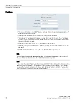
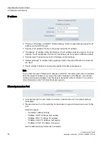
Page 92: ...this area you define which rights are associated with which password Several users can access the Sm rtServer simultaneously via a password If no password is specified then users with the appropriate authorization can log in without a password Password for user 1 First password for access to the HMI device Default setting No password User 1 is allowed to remote control the panel Option to activate...

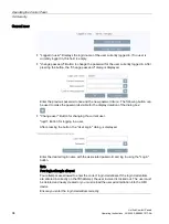
Page 93: ...t number for access via the Sm rtClientapplication Default value is 5900 5 6 Security 5 6 1 User management A convenient user administration is available to you under User management The user administration is configured in WinCC transferred to the HMI device and managed on the HMI device To transfer the user administration from WinCC to the HMI device the option Keep current user administration d...

Page 94: ... can be used to make the passwords visible for the display duration of the dialog box Change user Button for changing the current user login Button for logging in a user After pressing the button the User Login dialog is displayed Enter the desired login name with the associated password and log in using the Login button Note Four login attempts allowed Four attempts are allowed to enter the corre...

Page 95: ...rting and exporting the user administration the User administration function right is required the Import export users function right which can be configured in WinCC is not re quired The user list displays the users available on the HMI device with the following user characteristics Name Login name of the user Groups User groups to which the user is assigned LogOffTime Maximum permissible login t...

Page 96: ...MI Administrator User administration Remote access remote configuration Web access monitoring HMI Operator Web access operation monitoring HMI Monitor Web access monitor Note Assign the Control Panel access function right via a user defined role There is no system defined role in WinCC to which the Control Panel access function right is assigned To give a user full access to the Control Panel of t...

Page 97: ...ther properties of a public key For information on handling certificates observe the General safety instructions Page 21 section Certificates on the device Certifcate store Selection list for filtering the certificate list according to the following certificate types Trusted Authorities for trustworthy certificates My Certificates for your own certificates Other Certificates for other certificates...

Page 98: ... under Password and confirm the password under Iteration Delete Button to delete the currently selected certificate in the certificate list Note The selected certificate is deleted immediately without prompt Certificate details Certificate name Name of the certificate Status Status of the certificate on the HMI device Trusted or Revoked Thumbprint Character string to prove the authenticity of the ...

Page 99: ...le password protection for control panel option the Access to control panel is restricted dialog box is displayed Log in as a user with the Control Panel access function right to activate the password protection for the Control Panel Use the following button to make the password visible for the display duration of the dialog Note Four login attempts allowed Four attempts are allowed to enter the c...

Page 100: ...aces Under Hardware interfaces change the settings for accessing the storage media interfaces You can deactivate one or more interfaces to protect the HMI device from unauthorized external access The system memory card interface cannot be deactivated Data memory card slot Activate data memory card slot Option to enable or disable the interface for the data memory card The default setting is Activa...

Page 101: ...ver on the network NOTICE Time synchronization required for time dependent reactions A malfunction may occur in the plant if the date and time are not synchronized and time dependent reactions are triggered in the plant via the HMI device To avoid malfunctions use automatic time synchronization via one or more NTP servers Date and Time Date Display field with the current date Current time Display ...

Page 102: ...t Date and Time button is used to save the setting Synchronize time with a NTP Network Time Protocol Server Option for automatic time synchronization via an NTP server If you select this option the following parameters for specifying time synchronization via NTP servers are displayed below the options Enter the desired synchronization interval under Update rate value range 10 to 86400 seconds 1 da...

Page 103: ...dustrial Ethernet This allows the HMI device to be accessed as an alternative to direct communication as follows Via routing through a controller Via a switch or via a router in the local network If possible use the Ethernet data channel which offers higher performance than PN IE Only use the Ethernet data channel for the Update operating system via WinCC function Encrypted project transfer Passwo...

Page 104: ...tem are retained even after the update of the operating system The external interfaces become activated again default setting see section Hardware interfaces Page 100 The time zone is reset to the default setting UTC Coordinated Universal Time see section Date and time Page 101 Use a SIMATIC SD memory card with 32 GB or more or an industrial USB flash drive to load the firmware Firmware files for ...

Page 105: ...e files on external storage The list shows all firmware files that can be loaded into the HMI device Select the desired firmware master file fwf from the list Update OS Button for starting the loading process The HMI device restarts after the Update OS button is pressed The loading process then begins A dialog with a progress bar is displayed on the HMI device for each firmware file The HMI device...

Page 106: ...e HMI device a backup may require up to 20 GB of memory Make sure that the storage medium has sufficient free space Recommendation At least 5 GB of free space on the storage medium Remote access to the HMI device is not possible during the backup process Do not turn off the HMI device during the backup process Choose backup type Select one of the following options Complete backup Backup all data o...

Page 107: ...up is started and a dialog with a progress bar is displayed for each backup file The HMI device is restarted again after the completion of the backup process The main window of the Control Panel is displayed after the restart The data of the HMI device are saved on the storage medium Note Do not rename backup files on the data storage medium If you change the name of the backup files on the data s...

Page 108: ...ized as system memory card by the HMI device System memory card in a device of a different type If you use the system memory card of an HMI device in an HMI device of a different type an error message is displayed For service purposes use a system memory card only in HMI devices of the same type Do not remove the system memory card for automatic backup during operation If the Automatic backup func...

Page 109: ...MATIC SD memory card in slot X50 Starting automatic backup Status message after pressing the button Start the system memory card is being prepared Synchronizing data Status message during preparation of the system memory card Automatic backup active Status message when preparation of the system memory card has been completed the Automatic backup function was successfully activated Resetting system...

Page 110: ...sage Starting automatic backup is displayed The system memory card is being prepared Note Do not remove the system memory card during the preparation If you remove the system memory card from the HMI device during the preparation the system memory card cannot be used for automatic backup Leave the system memory card in its slot during the preparation process The status message Synchronizing data i...

Page 111: ...the corresponding backup must first be loaded Automatic backup can then be continued 1 Insert the SIMATIC SD memory card with automatically backed up data in slot X50 The System memory card plugged dialog box is displayed 2 Press the OK button The window Service and Commissioning Restore opens in the Control Panel 3 Select a backup file and press the Restore button The following dialog box indicat...

Page 112: ...kup To continue the automatic backup on the HMI device reactivate the Automatic backup function under Service and Commissioning Automatic Backup in the Control Panel See also Accessories Page 16 Backup Page 106 Changing the memory card Page 72 5 9 5 Restore Under Restore you can restore the backup of an HMI device from a storage medium Remote access to the HMI device is not possible during the res...

Page 113: ...the data source from the HMI device During the restore process a dialog with a progress bar is displayed for each backup file loaded The HMI device is restarted again after the completion of the restore process The main window of the Control Panel is displayed after the restart The data from the storage medium is now restored on the HMI device Note System behavior when the process is interrupted I...

Page 114: ...urposes e g to display trace outputs from scripts If you start the HMI device in maintenance mode the Tracing function is automatically enabled See also FAQ on configuring Trace Viewer https support industry siemens com cs ww en view 109777593 5 10 Apps The following options are available for managing apps on the HMI device under Apps Install or uninstall SIMATIC Apps via SIMATIC Edge or change th...

Page 115: ...ngs The following entries are available in the above example for the delivery condition SIMATIC Apps SIMATIC Edge Page 116 Add ons Doc Viewer E Mail Client File Browser Media Player PDF Viewer Printer Configuration Web Browser You can find the description of the settings for the apps under Add ons in section Add ons Page 117 Settings App Management Page 119 Note Data input in apps For data input i...

Page 116: ...t setting is deactivated Open edge management Button to open the local Edge Management web page To manage Edge apps on the HMI device log in to Edge Management using the Sign in link Log in as a user who has been assigned the Control Panel access function right in the configuration Siemens Industrial Edge You can find detailed information on Siemens Industrial Edge and Edge Management on the Edge ...

Page 117: ...th the Doc Viewer you can view and edit documents such as text or Word files Note Do not use the Doc Viewer to edit files that have been saved via the Runtime software or a system function These files include for example parameter sets that were exported to a tsv file Yes E Mail Client With the E Mail Client you can connect to your e mail accounts receive e mails send e mails and import mail files...

Page 118: ...ction Name of start script Depending on the desired app use of the following scripts for the Name of start script App to be started Associated start script Doc Viewer runLibreoffice sh E Mail Client runEvolution sh File Browser runThunar sh Media Player runVLC sh PDF Viewer runOkular sh Web Browser runChromium sh Under Program parameters you can specify which file is to be opened Example Open the ...

Page 119: ...er Add ons Uninstall Button to uninstall the selected app Recommendation Uninstall apps that you do not need Note Uninstallation cannot be undone An uninstalled app cannot be installed again To get back all apps pre installed in the delivery state you must restore the factory settings of the HMI device Configure Button to change the settings of the selected app see section Add ons Page 117 See als...

Page 120: ...Operating the Control Panel 5 10 Apps Unified Comfort Panels 120 Operating Instructions 03 2020 A5E46641217 AA ...

Page 121: ...the configuration phase the project is transferred to HMI device followed by the process control phase Transferring the project to the HMI device The project must be transferred to the HMI device to be used in process control You have the following options for the transfer Transfer the project from a configuration PC to the HMI device see section Transferring a project with WinCC Page 125 Insert a...

Page 122: ...ic backup Page 108 Restore the backup file of an identical HMI device from an external storage medium see section Restore Page 112 If the operating system cannot be updated with the above options then you must reset the HMI device to factory settings You can reset the HMI device to the factory settings in the following ways If the HMI device starts and you have access to the Control Panel proceed ...

Page 123: ...this mode there is no communication between the HMI device and the controller Even though the HMI device can be operated it cannot exchange data with the controller Online operating mode In this operating mode there is a communication connection between HMI device and the controller or between HMI device and the configuration PC In online operation between HMI device and controller operate the pla...

Page 124: ... Ethernet x x The PN IE protocol is not recommended for backup and restore due to its low bandwidth The X20 RS422 485 interface is designed for connecting controllers from other manufacturers Do not use the X20 interface for data transfer between the configuration PC and the HMI device 6 4 Setting the PG PC interface To establish Ethernet communication between the configuration PC and the HMI devi...

Page 125: ...ace with the highest bandwidth 3 In the Control Panel of the HMI device select Network and Internet Ensure that the port selected for data transmission is activated for the interface used Activate this port for use 4 In the Control Panel of the HMI device select Service and Commissioning Transfer 5 Make sure that the Enable transfer option is activated and select the setting Ethernet or PN IE unde...

Page 126: ...software The project can still be loaded with this setting Warning The setting in the Action column can be changed Note that the setting on the HMI device is different from the setting in the configuration software The project can be loaded after the setting in the Action column has been changed Error It is not possible to change the setting in the Action column The project cannot be loaded Adapt ...

Page 127: ...runtime option must be cleared Reset logs Selection list for resetting or keeping all logs If you select Reset all the data of all data logs alarm logs and context logs are deleted on the HMI device HMI Runtime This area contains information about runtime and firmware operating system version of the HMI device Secure transfer In this area you determine whether the project is transferred encrypted ...

Page 128: ...ject is running on the HMI device close the project 2 Connect the HMI device to the configuration PC via the X1 or X2 interface If possible use the X2 interface with the highest bandwidth 3 In the Control Panel of the HMI device select Network and Internet Ensure that the port selected for data transmission is activated for the interface used Activate this port for use 4 In the Control Panel of th...

Page 129: ...e master file brf together with all associated backup files 0 1 2 etc If one of the files is missing the backup cannot be loaded Backup to data storage medium on the HMI device As an alternative to the configuration PC you can also save the data via the Control Panel of the HMI device on a data storage medium that is directly connected to the HMI device see section Backup Page 106 Restore from the...

Page 130: ...kup 12 Click Start Restore The restore process is started A dialog with a progress bar is displayed both in ProSave and on the HMI device for each backup file loaded The update operation can take time depending on the connection selected Do not switch off the HMI device during the restore process and do not disconnect the data source from the HMI device Note System behavior when the process is int...

Page 131: ...vated again default setting see section Hardware interfaces Page 100 The time zone is reset to the default setting UTC Coordinated Universal Time see section Date and time Page 101 When the operating system is reset to factory settings all data of the HMI device is deleted and all settings in the Control Panel are reset to factory settings The operating system is contained in several firmware file...

Page 132: ...the HMI device during data transfer If you switch off the HMI device while the operating system of the HMI device is being updated the HMI device no longer starts You must repeat the procedure Do not turn off the HMI device during data transfer Procedure To update the operating system follow these steps 1 If a project is running on the HMI device close the project 2 Connect the HMI device to the c...

Page 133: ...update operation can take time depending on the connection selected Result The operating system of the HMI device has been updated to the version of the selected firmware See also Overview and important notes Page 131 Update OS Page 104 6 7 3 Resetting an HMI device to factory settings via ProSave If the operating system on the HMI device is no longer functional you must reset the HMI device to fa...

Page 134: ...ection Select Ethernet Connection parameters Specify an IP address or computer name for the HMI device The IP address must be located in the subnet of the configuration PC 8 Enter the following data in the OS Update tab Under Opening select the path and file name of the firmware master file fwf containing the desired operating system Select the option Reset to factory settings Under MAC enter the ...

Page 135: ...of the HMI device The HMI device is designed for low maintenance operation However you should clean the glass front regularly Observe the information on chemical resistance https support industry siemens com cs ww en view 39718396 Important notes Note Avoid unintentional responses during cleaning If you clean the glass front when it is switched on you may cause inadvertent operations via the touch...

Page 136: ...ed after the HMI device is switched on you can start the HMI device in maintenance mode by clicking the Reboot in maintenance mode button Follow the description in section Resetting an HMI device to factory settings via ProSave Page 133 If the HMI starts with the boot splash screen and detects the corrupt operating system the HMI automatically switches to maintenance mode The Maintenance Mode dial...

Page 137: ... want to update the operating system Procedure Proceed as follows 1 Turn off the power supply of the HMI device 2 Press the Maintenance button Use a blunt sufficiently sturdy tool made of non conductive material diameter approx 5 mm You will find the Maintenance button in the opening between the two interfaces X1 and X2 Be sure to hit the button accurately and do not slide the tool off the button ...

Page 138: ...he sender ordered a new HMI device The address is Siemens AG Digital Industries Retouren Center c o Geis Service GmbH Tor 1 4 Kraftwerkstraße 25a 91056 Erlangen Germany Spare parts Spare parts and accessories for the HMI device can be found in section Accessories Page 16 7 5 Recycling and disposal Due to the low levels of pollutants in the HMI devices described in these operating instructions they...

Page 139: ...nts of the following EU directives and conform with the harmonized European standards EN published in the official gazettes of the European Union and confirmed in the EU Declarations of Conformity 2014 35 EU Electrical equipment for use within certain voltage limits Low Voltage Directive 2014 30 EU Electromagnetic Compatibility Directive EMC Directive 2011 65 EU Directive of the European Parliamen...

Page 140: ...word Declaration of Conformity Unified Comfort Panels certificates https support industry siemens com cs ww en ps 26033 cert UL approval Observe the following notes The device shall be supplied from an isolating source Only for use in LAN not for connection to telecommunication circuits Underwriters Laboratories Inc to UL 61010 2 201 E116536 CSA C22 2 No 61010 2 201 or Underwriters Laboratories In...

Page 141: ...must therefore be installed so that it is only accessible to service personnel or users that are aware of the reason for restricted access and the required safety measures at an ambient temperature higher than 45 C WARNING The equipment is intended to be installed within an enclosure control cabinet The inner service temperature of the enclosure control cabinet corresponds to the ambient temperatu...

Page 142: ... 2015 Ed 5 1 IEC 60079 31 2013 Ed 2 Approvals Ex ec IIC T4 Gc Ex tc IIIC T70 C Dc IEC 61010 2 201 The devices meet selected requirements and criteria of the IEC 61010 standard safety regulations for electrical equipment for measurement control and laboratory use Part 2 201 Special requirements for control equipment IEC 61131 The devices meet the requirements and criteria of IEC 61131 2 Programmabl...

Page 143: ...toms union of Russia Belarus and Kazakhstan Declaration of conformity according to Technical Regulations of the Customs Union TR CU WEEE label European Union Disposal instructions observe the local regulations and the section Recycling and disposal Page 138 Marine approvals The following marine approvals are provided for the device ABS American Bureau of Shipping BV Bureau Veritas DNV GL Det Norsk...

Page 144: ...th regard to pulse shaped interference The precondition for electromagnetic compatibility is that the device meets the specifications and guidelines for electrical installation Pulse shaped interference Tested with Degree of severity Electrostatic discharge in accordance with IEC 61000 4 2 Air discharge 8 KV 3 Contact discharge 6 kV front Contact discharge 4 kV rear 2 Bursts high speed transient i...

Page 145: ... amplitude modulation of 1 kHz in the 150 kHz to 80 MHz range Magnetic field strength according to IEC 61000 4 8 50 60 Hz 30 A m rms Emission of radio interference The following table shows the interference emission from electromagnetic fields according to EN 61000 6 4 measured at the following distance Radiated emission emitted interference Frequency range Measuring distance Interference emission...

Page 146: ...068 2 6 5 8 4 Hz deflection 3 5 mm 8 4 500 Hz acceleration 1 g Shock according to IEC 60068 2 27 250 m s2 6 ms 1000 shocks 8 4 2 Operating conditions The following information applies to a device installed according to the specifications in these operating instructions The device was tested based on IEC 60721 3 3 Class 3M3 with the following additions and restrictions Type of condition Permitted r...

Page 147: ...ice that is transported in the original packaging and weather proof packaging and stored for some time The device was tested according to IEC 60721 3 2 Class 2K11 with the following additions and restrictions Type of condition Permitted range Temperature 20 60 C Atmospheric pressure 1140 660 hPa corresponds to an elevation of 1000 to 3500 m Relative humidity 10 90 Pollutant concentration SO2 0 5 p...

Page 148: ...ting in portrait format Vertical 0 40 C Inclined maximum inclination 35 0 35 C Atmospheric pressure 2 operation elevation 1140 795 hPa corresponds to an elevation of 1000 to 2000 m Relative humidity From 10 90 no condensation at the rear of the device Pollutant concentration SO2 0 5 ppm relative humidity 60 no condensation at the rear of the device H2S 0 1 ppm relative humidity 60 no condensation ...

Page 149: ... in landscape format without inclination 8 6 Information on insulation tests protection class and degree of protection Insulation test The insulation strength is verified in the type test with the following test voltages according to IEC 61010 2 201 and IEC 61131 2 Circuit Insulation tested with type test Rated voltage Ue 24 V 707 V DC to other circuits to ground Ethernet connector 1500 V AC Degre...

Page 150: ...ction Front When mounted IP65 according to IEC 60529 Type 4X Type 12 indoor use only front face only according to UL50 Rear IP20 Protection against contact with standard test probes There is no protection against the ingress of water dust and noxious gas The degree of protection at the front can only be guaranteed if the mounting seal lies flush against the mounting cutout Observe the correspondin...

Page 151: ...Technical information 8 7 Dimension drawings Unified Comfort Panels Operating Instructions 03 2020 A5E46641217 AA 151 8 7 2 Dimension drawings of the MTP1000 Unified Comfort ...

Page 152: ...Technical information 8 7 Dimension drawings Unified Comfort Panels 152 Operating Instructions 03 2020 A5E46641217 AA 8 7 3 Dimension drawings of the MTP1200 Unified Comfort ...

Page 153: ...Technical information 8 7 Dimension drawings Unified Comfort Panels Operating Instructions 03 2020 A5E46641217 AA 153 8 7 4 Dimension drawings of the MTP1500 Unified Comfort ...

Page 154: ...Technical information 8 7 Dimension drawings Unified Comfort Panels 154 Operating Instructions 03 2020 A5E46641217 AA 8 7 5 Dimension drawings of the MTP1900 Unified Comfort ...

Page 155: ...Technical information 8 7 Dimension drawings Unified Comfort Panels Operating Instructions 03 2020 A5E46641217 AA 155 8 7 6 Dimension drawings of the MTP2200 Unified Comfort ...

Page 156: ... Half Brightness Life Time MTBF 1 50000 h Pixel error class in accordance with ISO 9241 307 I 1 MTBF Operating hours after which the maximum brightness is reduced by half compared to the original value MTBF is increased by using the integrated dimming function for example time controlled via screensaver or centrally via PROFIenergy Input device Unified Comfort HMI device MTP700 MTP1000 MTP1200 Mul...

Page 157: ...d voltage range 19 2 V 28 8 V Mains and voltage buffering time 20 ms Rated current at 24 V DC without loads 0 45 A 0 5 A 0 6 A Rated current load dependent 0 45 1 0 A 0 52 1 1 A 0 6 1 3 A Power consumption without loads 1 10 8 W 12 5 W 14 4 W Inrush current I2t 0 5 A2s Maximum permitted transient 35 V 500 ms Minimum time between two transients 50 s Internal protection Yes 1 The power loss generall...

Page 158: ...s Life Time MTBF 1 50000 h 30000 h Pixel error class in accordance with ISO 9241 307 I 1 MTBF Operating hours after which the maximum brightness is reduced by half compared to the original value MTBF is increased by using the integrated dimming function for example time controlled via screensaver or centrally via PROFIenergy Input device Unified Comfort HMI device MTP1500 MTP1900 MTP2200 Multi tou...

Page 159: ...ed voltage range 19 2 V 28 8 V Mains and voltage buffering time 20 ms Rated current at 24 V DC without loads 0 7 A 1 2 A 1 0 A Rated current load dependent 0 7 1 3 A 1 2 A 1 7 A 1 0 1 5 A Power consumption without loads 1 16 8 W 28 8 W 24 0 W Inrush current I2t 0 5 A2s Maximum permitted transient 35 V 500 ms Minimum time between two transients 50 s Internal protection Yes 1 The power loss generall...

Page 160: ... interfaces 8 9 1 DC24V X80 Power supply 24 V DC 2 pin Pin Meaning 1 24 V DC 2 Ground 8 9 2 RS422 485 X20 Serial interface 9 pin sub D socket female Pin Assignment for the RS422 Assignment for the RS485 1 NC NC 2 NC NC 3 TxD Data signal B 4 RxD RTS 5 GND 5 V floating GND 5 V floating 6 5 VDC floating 5 VDC floating 7 NC NC 8 TxD Data signal A 9 RxD NC ...

Page 161: ...ut 2 Tx Data output 3 Rx Data input 4 NC Not assigned 5 NC Not assigned 6 Rx Data input 7 NC Not assigned 8 NC Not assigned 8 9 4 PROFINET LAN X2 PROFINET LAN 10 100 1000 Mbps RJ45 socket Pin Name Meaning 1 D1 Bi directional data 1 2 D1 Bi directional data 1 3 D2 Bi directional data 2 4 D3 Bi directional data 3 5 D3 Bi directional data 3 6 D2 Bi directional data 2 7 D4 Bi directional data 4 8 D4 B...

Page 162: ...nication with controllers Number of connections The Unified Comfort Panels support a maximum of 16 connections to S7 controllers and 16 parallel connections via SIMATIC HTTP Protocol Controllers The following controllers and communication drivers are supported by the HMI devices SIMATIC S7 1500 SIMATIC S7 1200 SIMATIC S7 300 400 SIMATIC S7 200 LOGO SIMOTION SIMATIC HTTP protocol Additional control...

Page 163: ...ion to the specified limits observe the restrictions imposed by configuration memory resources Tags Unified Comfort HMI device Display diagonal 12 Display diagonal 15 Number of tags in the project 8000 Number of elements per array 1600 Alarms Unified Comfort HMI device Display diagonal 12 Display diagonal 15 Number of alarm classes 32 Number of discrete alarms 9000 Number of analog alarms 300 Leng...

Page 164: ...er set types 750 Number of parameter set type elements 1000 Number of parameter sets 2000 Reserved memory for data records in the internal flash 1 12 MB 1 Expansion via memory card in slot X51 or USB flash drive at interface X61 or X62 Logs Unified Comfort HMI device Display diagonal 12 Display diagonal 15 Number of logs 50 Number of logging tags SQLite 5000 Number of logging tags Microsoft SQL Nu...

Page 165: ...jects 6000 Number of text elements 60000 Scripts Unified Comfort HMI device Display diagonal 12 Display diagonal 15 Number of Java scripts 600 Number of functions per function list 25 Scheduler Unified Comfort HMI device Display diagonal 12 Display diagonal 15 Number of tasks time or event triggered 70 Communication Unified Comfort HMI device Display diagonal 12 Display diagonal 15 Number of S7 co...

Page 166: ...3 2020 A5E46641217 AA User administration Unified Comfort HMI device Display diagonal 12 Display diagonal 15 Number of roles 50 Number of predefined function rights 20 Number of users 200 Project Unified Comfort HMI device Display diagonal 12 Display diagonal 15 Size of the project files on the device 100 MB ...

Page 167: ... When contacting your local representative or Technical Support please have the following information at hand MLFB of the device BIOS version for industrial PC or image version of the device Other installed hardware Other installed software Firmware and software Firmware and software for your HMI device are constantly being further developed Check regularly whether software updates or patches are ...

Page 168: ...ent type has been inserted Replace the system memory card with the system memory card of a device of the same type You can use the system memory card with the device without using the data of the system memory card In this case all the data in the System Card SIMATIC HMI Active folder will be deleted A 3 Application examples and FAQs Application examples You can find application examples on the In...

Page 169: ...crypted parameters which are relevant to troubleshooting because they provide a reference to the source code of the runtime software These parameters are output after the text Error code Observe the notes on configuring system alarms and using the alarm buffer in the section Memory concept Page 69 Description of the system alarms You can find a list of system events for your HMI device in the TIA ...

Page 170: ...Technical Support A 5 Information about the manufacturer Unified Comfort Panels 170 Operating Instructions 03 2020 A5E46641217 AA ...

Page 171: ...information on the type of the potential hazard and enable you to identify risks and implement countermeasures ISO 7000 No 0434B DIN ISO 7000 No 0434B Attention only relevant for modules with Ex approval Observe the instructions ISO 7010 M002 Must be installed by qualified electricians only IEC 60417 No 6182 Mechanical load for HMI devices Connection cables must be designed for the ambient tempera...

Page 172: ...46641217 AA Symbol Meaning Reference Only for industrial applications and indoor areas control cabinet Device is to be integrated into a control cabinet Install devices approved for Ex Zone 2 in a control cabinet with at least IP54 Install devices approved for Ex Zone 22 in a control cabinet with at least IP6x ...

Page 173: ... I O DSN Data Source Name DSR Data Set Ready DTR Data Terminal Ready IO Input and Output ESD Components and modules endangered by electrostatic discharge EMC Electromagnetic Compatibility EN European standard ES Engineering System ESD Components and modules endangered by electrostatic discharge GND Ground HF High Frequency HMI Human Machine Interface IEC International Electronic Commission IF Inte...

Page 174: ...ered Jack Type 45 RTS Request to send RxD Receive Data SD Memory Card Abbreviation for Secure Digital Memory Card SELV Safety Extra Low Voltage SP Service Pack SUB D Subminiature D plug TAB Tabulator TCP IP Transmission Control Protocol Internet Protocol TFT Thin Film Transistor TxD Transmit Data UL Underwriter s Laboratory USB Universal Serial Bus UPS Uninterruptible power supply WINS Windows Int...

Page 175: ...Configuration software is used to create projects used for the purpose of process visualization WinCC represents such configuration software for example Controller Controller is a general term for devices and systems with which the HMI device communicates for example SIMATIC S7 Degree of protection The degree of protection specifies a standard of electronic equipment for a variety of ambient condi...

Page 176: ...on the motherboard Half Brightness Life Time Time period after which brightness is reduced to 50 of the original value The specified value depends on the operating temperature HMI device An HMI device is a device used for the operation and monitoring of machines and plants The machine or plant states are visualized on the HMI device by means of graphic objects The operator controls of the HMI devi...

Page 177: ... and monitored on an HMI device Process visualization Process visualization is the representation of technical processes by means of text and graphic elements Configured plant screens allow the operator to use input and output information to intervene in active plant processes Project A project contains information on the visualization of the automation process and is created using a configuration...

Page 178: ...is interconnected with the controller Trade goods In addition to their own accessories Siemens AG also offers high quality accessories from well known manufacturers as trade goods Trade goods are qualified in a brief power up test but do not undergo a system test by Siemens AG The technical properties of trade goods can deviate from the properties guaranteed by comparable products of the Siemens A...

Reviews: