Copyright © Siemens AG 2010. All rights reserved.
Page
86
ERTEC 400 Manual
Technical data subject to change
Version 1.2.2
F
IQ
IR
Q
IR
Q
0
_
S
P
IR
Q
1
_
S
P
P
C
I_
IN
T
_
C
T
R
L
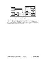
Figure 16: PCI Interrupt Handling
After a reset, PCI signal SERR_N is only generated from the PCI bridge (address parity error).
IRT interrupts IRQ0_HP and IRQ_IRT_API_ERR (synchronization problems in the IRT-API) can be enabled
according to the setting in the “PCI_INT_CNRL” system control register. Interrupt output SERR_N is a PCI-
synchronous signal. When used, the IRQ0_HP and IRQ_IRT_API_ERR interrupts are synchronized to the PCI
clock and kept active for the duration of one PCI clock cycle.


