background image

Building Technologies


 A6V10213263_h_--_--

Fire Safety & Security Products 


02.2011


Auxiliary terminals 

For detector base DB721-CN / DB720-CN 

1

2

1


Connection terminals: 1…2.5 mm

2


Micro terminals: 0.28…0.5 mm

2


Designation plate, detector locking device 

5

3

4

A.

B.

Designation plate 

Detector base 

A.


 Insert the detector in the detector base. 

B.


 Insert the hexagonal wrench provided in the bore hole 

 on the detector housing and tighten the grub screw. 


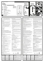
Connection diagram, addressed 

1a

1b

5

6

1a

1b

5

6

1a

1b

5

6

1a

1b

5

6

1a

1b

5

6

+

+

+

2

2

2

1

3

4

4

+

3

3

2

2

+


Control panel 

Detector base DB721-CN / DB720-CN 

Connection terminal DBZ1190-XX 

External alarm indicator 

Inserting the detector 

Insert the detector (1) in the detector base (2), turning 

clockwise. You must be able to hear and feel the detector 

snap in. 
 

2

1


Removing the detector 

Turn the detector (1) anticlockwise to remove it from the 

detector base (2). 


Summary of Contents for DB721-CN

Page 1: ...urity Products DB721 CN DB720 CN RS720 LP720 en Detector base with loop contact Detector base Detector base seal Detector locking device de Meldersockel mit Schlaufkontakt Meldersockel Meldersockel Dichtung Melderarretierung en Installation de Montage ...

Page 2: ...se 3 Screws with max Ø of 4 mm 4 Min 40 mm 5 Max 90 mm 6 Surface cable with max Ø of 8 mm Installation in humid or wet environments 9 10 1 Detector base seal RS720 2 Detector base Cable entry 1 2 3 3 1 Detector base 2 The conductor loops must be placed flat in the base bottom 3 Connection terminals with screws The detector bases contain four screw terminals Terminal name Connection 1a Connection f...

Page 3: ... the hexagonal wrench provided in the bore hole on the detector housing and tighten the grub screw Connection diagram addressed 1a 1b 5 6 1a 1b 5 6 1a 1b 5 6 1a 1b 5 6 1a 1b 5 6 2 2 2 1 3 4 4 3 3 2 2 1 Control panel 2 Detector base DB721 CN DB720 CN 3 Connection terminal DBZ1190 XX 4 External alarm indicator Inserting the detector Insert the detector 1 in the detector base 2 turning clockwise You ...

Page 4: ...rauben max Ø 4 mm 4 Min 40 mm 5 Max 90 mm 6 Aufputzkabel bis max Ø 8 mm Montage in feuchter nasser Umgebung 9 10 1 Meldersockel Dichtung RS720 2 Meldersockel Kabeleinführung 1 2 3 3 1 Meldersockel 2 Die Leiterschlaufen müssen im Sockelboden flach anliegen 3 Anschlussklemmen mit Schrauben Die Meldersockel enthalten vier Schraubklemmen Klemmenbezeichnung Anschluss 1a Anschluss externer Alarmindikato...

Page 5: ... beigelegtem Sechskantschlüssel durch die Bohrung im Meldergehäuse den Gewindestift festschrauben Anschlussschema adressiert 1a 1b 5 6 1a 1b 5 6 1a 1b 5 6 1a 1b 5 6 1a 1b 5 6 2 2 2 1 3 4 4 3 3 2 2 1 Zentrale 2 Meldersockel DB721 CN DB720 CN 3 Verbindungsklemme DBZ1190 XX 4 Externer Alarmindikator Melder einsetzen Drehen Sie den Melder 1 im Uhrzeigersinn in den Meldersockel 2 ein Der Melder muss hö...

Page 6: ...B720 CN S54319 F4 A101 en Detector base de Meldersockel RS720 S54319 F8 A1 en Detector base seal de Meldersockel Dichtung FDBZ291 A5Q00002621 en Designation plate de Melderkennzeichen LP720 S54319 F9 A1 en Detector locking device de Melderarretierung DBZ1190 AA BPZ 4677080001 en Micro terminal 0 28 0 5 mm2 de Mikroklemme 0 28 0 5 mm2 DBZ1190 AB BPZ 4942340001 en Connection terminal 1 2 5 mm2 de Ve...

Reviews: