2
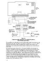
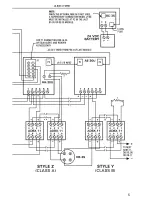
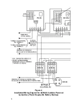
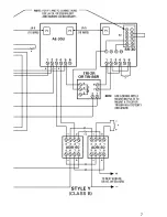
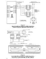
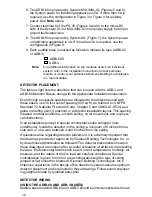
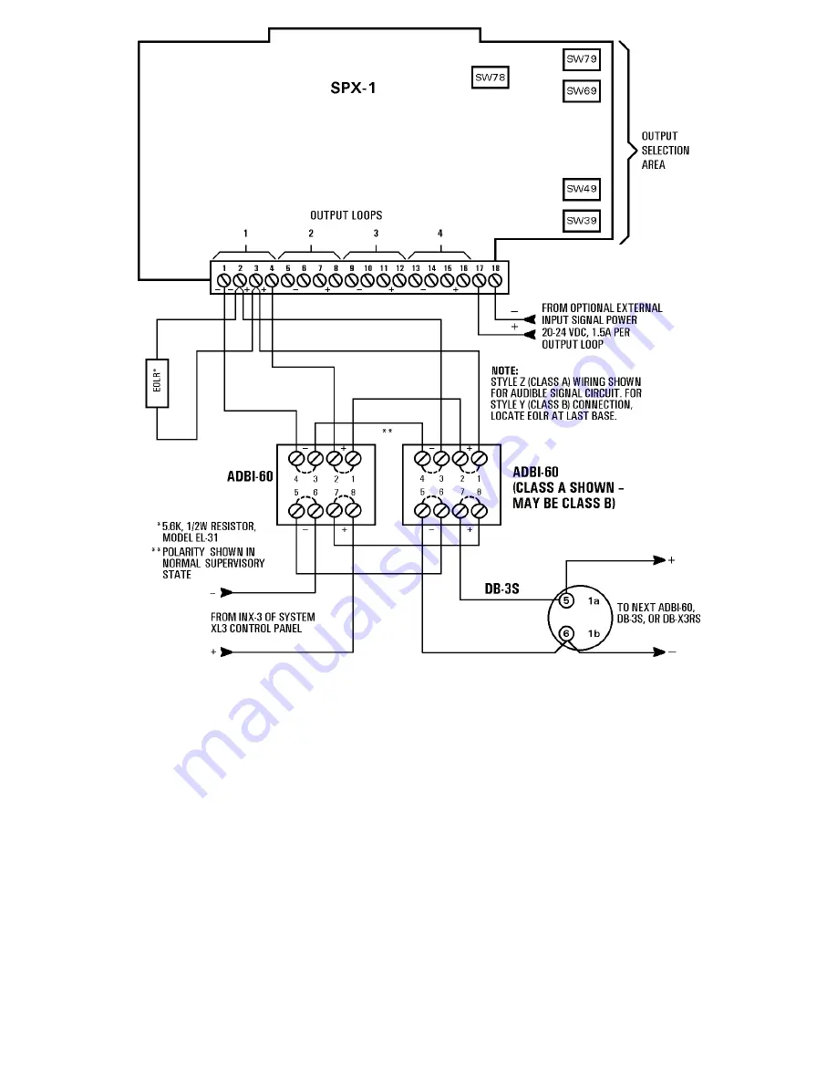
Several different configurations can provide audible signal circuit power to the
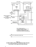
ADBI-60 at terminals 1 through 4, as shown in Figures 2, 3, 4, 5, 6, 7, and 8.
During the supervisory state (no alarms), the polarity of the power to all
ADBI-60s is in a reversed (off-normal) state, resulting in zero current flow to
each base.
Any alarm reported to System XL3 or System MXL/MXL-IQ activates the
TRI-2R or TRI-B6R module and triggers the AA-30U/AE-30U modules (See
Figures 3 and 4). The power to all ADBI-60s reverses polarity for normal
operation, but no audibles sound. The System XL3 or MXL/MXL-IQ may then
selectively command the ADBI-60, under programmed control, to sound via the
circuitry in the addressable detector plugged into each ADBI-60. For IXL
(ICON-1), the CE-S is programmed to follow the system alarm relay (See
Figures 7 and 8). Only those ADBI-60s connected to a detector in alarm will
sound. The ADBI-60 is UL 268 listed and meets the UL audibility sound output
requirement of 85 decibels at 10 feet.
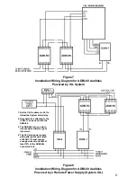
Figure 2
Installation/Wiring Diagram for ADBI-60 Audibles
Powered by System XL3

