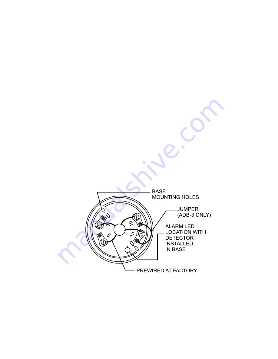
Mounting the Detector Base
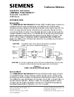
1. Route all wires out from the outlet box.
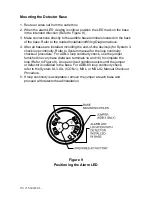
2. When the alarm LED viewing is critical, position the LED mark on the base
in the intended direction (Refer to Figure 9).
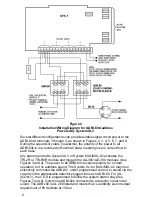
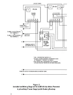
3. Make connections directly to the audible base terminals located on the back
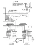
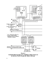
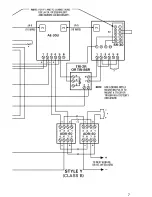
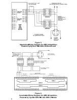
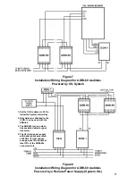
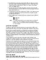
of the base. Refer to the related lnstallation/Wiring Diagram above.
4. After all bases are installed, including the end-of-line device(s) for System 3,
check loop continuity. Refer to System manual for the loop continuity
checkout procedure. For ADB-3 loop continuity check, use the jumper
furnished in every base (between terminals 1a and 1b) to complete the
loop (Refer to Figure 9). An open circuit condition exists until the jumper
or detector is installed in the base. For ADBI-60 loop continuity check,
refer to the System XL3, IXL (ICON-1), MXL, or MXL-IQ Manual Checkout
Procedure.
Figure 9
Positioning the Alarm LED
P/N 315-086238-5
5. If loop continuity is acceptable, remove the jumper at each base and
proceed with detector head installation.

