background image

9

6.3

Positionsmeldeschalter anschließen

Es  sind  2  Arten  von  Positionsmeldeschaltern  für  die  Be-

triebs-, Prüf-, und Trennstellung vorhanden:
1. Meldeschalter,  die  nur  vom  Einschubrahmen  betätigt

werden  und  unabhängig  vom  Vorhandensein  des  Lei-

stungsschalters  funktionieren:  (3WX31  84-1JA**,  **  =

01, 11, 21). Montage und Anschließen siehe Betriebsan-

leitung 9239 9554 174 .

2. Meldeschalter,  die  vom  Einschubrahmen  und  vom  Lei-

stungsschalter gemeinsam betätigt werden (3WX31 84-

17B**,  **  =  01,  21).  Montage  und  Anschließen  siehe

Betriebsanleitung  9239  9630  174.

6.3

How to connect the position microswitches

There are 2 types of position switch for the connected, test

and  disconnected  position:
1. Position  switches  actuated  only  by  guide  frame  and

functioning  independently  of  presence  of  circuit-break-

er:  (3WX31  84-1JA-**,**  =  01,  11,  21).  Mounting  and

connecting see Operating instructions 9239 9554 174 .

2. Position switches actuated by guide frame and cir-

cuit-breaker  jointly  (3WX31  84-17B**,**  =  01,  21).

Mounting  and  connecting  see  Operating  instruc-

tions  9239 9630 174.

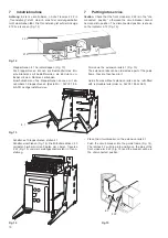
6.13 Schutzerden

Der  Einschubrahmen  ist  an  der  besonders  gekennzeich-

neten Bohrungen (Fig. 11a) an den Schutzleiter des Netzes

anzuschließen.

6.13 Earthing

Connect the guide frame to the PE conductor of the system

by means of the specially marked holes (Fig. 11a).

Links und rechts des Ein-

schubrahmens
On the left and right side

of the guide frame

Fig. 11a

Einschubrahmen  und  Einschubschalter,

Schutzerden

Guide frame and draw-out breaker, earthing

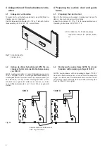
6.2

Anschließen der Hilfsleiter

Einschubschalter  sind  mit  automatisch  trennenden  Hilfs-

stromsteckern  ausgerüstet.  Der  Hilfsleiteranschluß  erfolgt

in  dem  Einschubrahmen.

6.2

Connecting the auxiliary conductors

Draw-out  circuit-breakers  are  fitted  with  automatically  dis-

connecting auxiliary plugs. The auxiliary plugs are connect-

ed in the guide frame.

10 mm

Stecker aufsetzen

Connect the plug

Leiter  abisolieren

Strip the conductor

Leiter  anschließen

Connect the conductor

Spätere Demontage der Stecker:

Schnappverbindung  lösen

Subsequent  removal:

Undo  snap  connection

Summary of Contents for 3WX31 83-8 Series

Page 1: ... 83 8 Guide frame 3WX35 83 8 3WX611 8 8 Alle Rechte vorbehalten All rights reserved Siemens AG 1989 Betriebsanleitung OperatingInstructions Bestell Nr OrderNo 3ZX1812 0WX31 2AN3 923995031740C Fig 1 Einschubrahmen Guide frame ...

Page 2: ...nft über die örtliche Siemens Niederlassung an fordern Außerdem weisen wir darauf hin daß der Inhalt dieser Betriebsanleitung nicht Teil einer früheren oder bestehen den Vereinbarung Zusage oder eines Rechtsverhältnisses ist oder dieses abändern soll Sämtliche Verpflichtungen von Siemens ergeben sich aus dem jeweiligen Kaufvertrag der auch die vollständige und allein gültige Gewährleistungsregelun...

Page 3: ...ndauerstrom Einschubrahmens Leistungsschalters Iu1 Frame size Type designation Type designation Continuous current of guide frame of draw out breaker rating Iu1 of breaker I 3WX611 8 8CA 3WS1 2 bis to 3WS1 4 630 bis to 1600 A II 3WX611 8 8DA 3WS1 6 1600 bis to 2500 A I 4 polig I 4 pole 3WX611 8 8CB 3WN1 2 bis to 3WS1 4 630 bis to 1600 A Die jeweilige Typenbezeichnung kann dem Typenschild an der re...

Page 4: ...ellung Test position Hauptstromkreis getrennt Hilfsstromkreise verbunden Schaltschranktür geschlossen Power circuits disconnected Auxiliary circuits connected Cubicle door closed 4 Betriebsstellung Connected position Hauptstromkreis und Hilfsstromkreise verbun den Schaltschranktür geschlossen Power and auxiliary circuits connected Cubicle door closed Verschieben direkt von Hand Move manually Versc...

Page 5: ...he front at the left Interlocks within the circuit breaker and and the guide frame ensure that the breaker is tripped as soon as the racking spindle is inserted cannot be closed while being racked from one position to another can be moved only in the tripped state accessory 3 Transportieren und Abstellen 3 Transporting and setting down Hinweis Einschubrahmen dürfen nur ohne eingeschobenen Lei stun...

Page 6: ...2 Umbau des Einschubrahmens 3WN1 für Lei stungsschalter mit einer Betriebsspannung von 1000 V 3WN1 Leistungsschalter mit einer Betriebsspannung von 1000 V verfügen über 2 Lichtbogenkammeraufsätze pro Lichtbogenkammer und damit über eine entsprechend grö ßere Bauhöhe Um auch diese Leistungsschalter im Ein schubrahmen ungehindert verfahren zu können muß das neue Hilfsleiterstecksystem um 30 mm höher...

Page 7: ...t herausragen Fig 8 Als Sicherungselemente Spannscheiben DIN 6796 verwen den 5 Installation Refer to the dimension drawings on catalog and manual for mounting dimensions and mounting holes The unit is mounted horizontally by means of four M8 screws The bolt on positions must not differ in heigt by more than 1 mm The front screws 2 122 must not protude from the guide rails 2 121 Fig 8 Use conical s...

Page 8: ...estigkeitsklasse 8 8 und Spannscheiben DIN 6796 zu verwenden Die Anschlußschienen müssen entsprechend Fig 10 ab gestützt werden 2 Einschubrahmen Guide frame 2 31 Anschlußflansch Connecting flange 2 311 Anschlußschiene Terminal bar 2 312 Anschlußschraube Terminal screw 2 313 Spannscheibe Conical spring washer 2 314 anlagenseitige Stromschienenabstützung Support of the connection busbars and the swi...

Page 9: ...cuit breaker jointly 3WX31 84 17B 01 21 Mounting and connecting see Operating instruc tions 9239 9630 174 6 13 Schutzerden Der Einschubrahmen ist an der besonders gekennzeich neten Bohrungen Fig 11a an den Schutzleiter des Netzes anzuschließen 6 13 Earthing Connect the guide frame to the PE conductor of the system by means of the specially marked holes Fig 11a Links und rechts des Ein schubrahmens...

Page 10: ...tungsschalter steht in Trenn stellung Place the circuit breaker on the extension rails 4 1 Push the circuit breaker into the guide frame Fig 14 The latches 4 3 will drop into position on the pins of the front cross arm 2 22 Fig 15 and the breaker will be in the disconnected position Fig 12 Klappschienen 4 1 herunterklappen Fig 13 Die Klappschienen können als Bestandteil des Ein schub rahmens mit b...

Page 11: ... Bedienpult annähernd angezeigt Fig 16 Fold up the extension rails and close the cubicle door When the circuit breaker is racked from one position to another behind the closed cubicle door each position will be indicated appoximately at the side of the control panel Fig 16 rot red blau blue grün green Prüfstellung Test position Trennstellung Disconnected position Betriebsstellung Connected positio...

Page 12: ...g bei ein und ausgeschaltetem Lei stungsschalter Die Sperre kann unter Wahrung der nötigen Umsicht über listet werden Fig 21 Hierzu mit Schraubendreher max 3 mm Durchmesser durch Bohrung 3 15 dahinterliegende Sperre zur Seite schwen ken Schaltschranktür öffnen Fig 19 Befettung kontrollieren und gegebenenfalls erneuern z B Topas L32 von Fa Klüber Lubrication München Check the greasing and if necess...

Page 13: ...n cannot be closed Padlocks with a max shackle diameter of 5 mm can be used Fig 22 Überlisten der Sperre gegen das Verschieben durch Kurbeln How to override the anti cranking lock 5 4 5 1 5 3 5 2 5 5 8 2 Sperre gegen Verschieben des Schalters bei geöffneter Schranktür Fig 22 Die Sperre verhindert das Verschieben durch Kurbel des Schalters bei geöffneter Schranktür Die Sperrvorrichtung kann unter W...

Page 14: ...ennstellung vorge nommen werden Wartungsarbeiten am Enschubrahmen dürfen nur bei span nungsloser Schaltanlage durchgeführt wer den Die Schalt anlage ist während der Arbeiten ge gen Wiedereinschaltung zu sichern For safety reasons do not undertake maintenance work on the circuit breaker while it is in the connected test or dis connected position Do not carry out any maintenance work on the guide fr...

Page 15: ...t breaker Operating Instructions 9239 9500 174 Vorhängeschloß entfernen Remove padlock Ursache Cause Einschubrahmen nicht in Trennstellung Guide frame not in disconnected position Befestigungsschrauben des Einschubrah mens ragen aus den Führungsschienen heraus Fixing screws on the guide frame protude from the guide rails Linke und rechte Gleitschiene vertauscht montiert Left and right hand guide r...

Page 16: ...vorbehalten Published by the Automation Drives Group Control and Distribution Schaltwerk Berlin D 13623 Berlin Federal Republic of Germany Subject to change Siemens Aktiengesellschaft Bestell Nr Order No 3ZX1812 0WX31 2AN3 923995031740C Bestell Ort Place of Order A D CD PD Log PCB Berlin PrintedintheFederalRepublicofGermany AG06 2002KbDe En ...

Reviews: