Functional Information
3TK2845 Multifunction Device Manual
2-4
GWA 4NEB 926 2087-22 DS 01
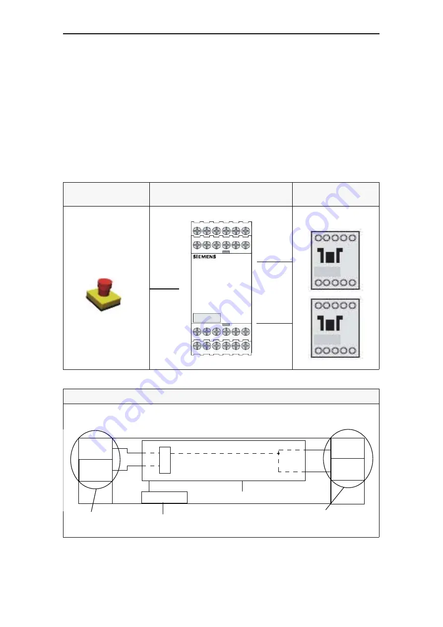
Use of the graphics
The device inputs (number and type) are shown in the sensor interface. The
safety logic is shown in the middle. The safety logic is used to explain the mode
of operation of the device (how the inputs affect the outputs). The type and
number of the enabling circuits or signaling outputs are shown in the actuator
interface. The setting possibilities (parameters) of the device are shown at the
lower end of the graphic. The legend explains the meaning of the symbols.
To simplify the presentation, the schematics only show those inputs and outputs
which are necessary to explain the safety logic. The power supply inputs as well
as the sensor or actuators which might be connected to the interfaces are not
shown since they are not relevant for the presentation of this function.
Detection (sensors)
Evaluation (safety relay)
Switching-off
(actuators)
EMERGENCY-STOP
Table 2-1: Use of the graphics
Device type
Table 2-2: Device type
.$6
%6
).
6
HO
).
6
HO
6
3DUDPHWHU;
Device parameter
Sensor interface
(inputs)
Actuator interface
(outputs/enabling circuits)
Safety logic
Summary of Contents for 3TK2845
Page 6: ...3TK2845 Multifunction Device Manual iv GWA 4NEB 926 2087 22 DS 01 ...
Page 38: ...Functional Information 3TK2845 Multifunction Device Manual 2 26 GWA 4NEB 926 2087 22 DS 01 ...
Page 44: ...Technical Data 3TK2845 Multifunction Device Manual 3 6 GWA 4NEB 926 2087 22 DS 01 ...
Page 66: ...3TK2845 Multifunction Device Manual 5 16 GWA 4NEB 926 2087 22 DS 01 ...
Page 68: ...3TK2845 Multifunction Device Manual GWA 4NEB 926 2087 22 DS 01 ...


