background image

1 - 1

Siemens AG


SPR8-125.034.02

Page 1 of 10

POLYMOBIL Plus

Medical Solutions

Rev. 02

03.05

CS PS 24


Requirements

1

Text emphasis

1

Symbols

1

Checks and adjustments that must be performed with radiation ON are identified by the 
radiation warning symbol.

This symbol means "Dangerous voltage".

Checks marked with this symbol are to be entered into the test certificate at the end of 
these instructions.

This symbol means "Attention, consult the documentation".

This symbol indicates components sensitive to Electro-Static Discharge (ESD).

DANGER indicates when there is an immediate danger that leads 
to death or serious physical injury.

WARNING indicates a risk of danger that may lead to death or to 
serious physical injury.

CAUTION used with the safety alert symbol indicates a risk of 
danger that leads to slight or moderate physical injury and/or 
damage to property.

NOTICE used without the safety alert symbol indicates a risk of 
danger that if disregarded leads or may lead to a potential situa-
tion which may result in an undesirable result or state other than 
death, physical injury or damage to property.

NOTE contains information provided with special emphasis to 
facilitate proper use of the equipment or proper execution of a 
procedure, i.e. hints, tips

.

DANGER

WARNING

CAUTION

NOTICE

NOTE

Summary of Contents for 12000

Page 1: ...5 The reproduction transmission or use of this document or its contents is not permitted without express written authority Offenders will be liable for damages All rights including rights created by patent grant or registration of a utility model _or_ design _are_ reserved SP From Serial No 12000 Start up Instructions ...

Page 2: ...s Disclaimer The installation and service of equipment described herein is to be performed by qualified personnel who are employed by Siemens or one of its affiliates or who are otherwise authorized by Siemens or one of its affiliates to provide such services Assemblers and other persons who are not employed by or otherwise directly affiliated with or autho rized by Siemens or one of its affiliate...

Page 3: ...g the controls and indicators 3 2 Check of the DAP measuring system optional 3 2 Checking the counterbalance system 3 3 Readjusting the counterbalance system with accessories attached 3 3 Checking the controls on the double slot diaphragm 3 4 Checking the exposure release with high voltage 3 4 Checking the exposure control 3 5 Custom programming 3 5 Checking coincidence of light and radiation fiel...

Page 4: ...0 4 Contents POLYMOBIL Plus SPR8 125 034 02 Page 4 of 4 Siemens AG Rev 02 03 05 CS PS 24 Medical Solutions Page ...

Page 5: ...es when there is an immediate danger that leads to death or serious physical injury WARNING indicates a risk of danger that may lead to death or to serious physical injury CAUTION used with the safety alert symbol indicates a risk of danger that leads to slight or moderate physical injury and or damage to property NOTICE used without the safety alert symbol indicates a risk of danger that if disre...

Page 6: ...on according to ARTD Part 2 Non compliance can lead to death to injuries or to material dam age X ray radiation Non compliance can lead to illnesses irreversible damage to body cells and to the genetic make up sever injuries up to death In work on the system in which radiation has to be released the radiation protection directives and the rules for radiation protec tion according to ARTD 002 731 0...

Page 7: ... more accessible on the D970 capacitor board at the connection point of capacitor C3 and on the right side of fuse F3 refer to Fig 1 LED s V1 V10 on D 970 go out at a significantly higher voltage level and therefore they are not reliable safety indicators If a fuse on the D 970 has responded high voltage may still be present at the affected capacitor even after a prolonged period of time The capac...

Page 8: ...e connected to nominal line voltages from 110 V AC through 230 V AC 10 and automatically self adjusts to the existing power line voltage After start up country specific tests are to be performed if required e g acceptance test according to RöV Germany X ray ordinance Acceptance test according to RöV Germany Required measurements can be partially transferred from the test protocol provided The foll...

Page 9: ...imulate no protective conductor connection During the measurement the power supply cable and additional connection cables with integrated protective conductors must be moved section by section to detect wire breaks The protective conductor resistance must not exceed 0 2 ohms Record the values as first measured values in the report Protective conductor resistance report stating the measuring points...

Page 10: ...eering rules for installation and maintenance ARTD 002 731 17 First measurement Perform the device leakage current measurement after completion of all other work Perform the measurement according to DIN VDE 0751 Part 1 see ARTD 002 731 17 and record the determined value as first measured value Measurement of the device leakage current according to the differential current method measuring arrangem...

Page 11: ...3 Measuring circuit for measuring the device leakage current according to the differential current method according to DIN VDE 0751 1 2001 10 Fig C6 for protective class I 1 System 2 Application part not available 3 Measuring arrangement integrated in the measuring instrument Fig 4 Measuring circuit for the direct measurement of the device leakage current according to DIN VDE 0751 1 2001 10 Fig C5...

Page 12: ... power supply unit e g repairs to the power up circuit or replacement of the mains filter perform the device leak age current measurement anew The same measuring conditions as in the first measurement apply Document the highest value determined in the repeat measurement in the available report Device leakage current report and assess it This value must not exceed the permissible leakage current va...

Page 13: ...g agent Do not use abrasive cleaning agents or organic solvents such as benzine alcohol or spot remover Do not spray water on the unit For additional information refer to the Instructions for use chapter Cleaning Disinfecting For the assessment the first measured value and the values docu mented during previous maintenance or safety checks must be compared with the measured values An abrupt rise o...

Page 14: ...POLYMOBIL Plus SPR8 125 034 02 Page 10 of 10 Siemens AG Rev 02 03 05 CS PS 24 Medical Solutions 1 10 Requirements This page intentionally left blank ...

Page 15: ... Bend the transport brackets on the crate cover upwards and remove the crate cover Bend the transport brackets on the side panels up and remove the side panels Place the side panel with the integrated ramp 1 Fig 1 down directly in front of the pallet and engage the retaining tabs Remove the plastic cover Fig 1 ...

Page 16: ...ing the strap 3 Fig 2 and the U shaped rail 4 Fig 2 Bring the foot pedal from the locking position into the maneuvering position 6 Fig 3 For other foot pedal positions refer to the operating instructions Remove the 2 Allen screws and the bracket 7 Fig 2 17 mm spanner opening from the stand trolley on the right and left side Push the POLYMOBIL Plus over the rail 8 Fig 3 and move it off the pallet v...

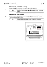
Page 17: ...asure the local power line voltage at the receptacle Attaching the warning label 3 Attach the warning label printed in the appropriate language item number 18 13 554 to the operating console 1 Fig 1 The system automatically self adjusts to the existing power line voltage The warning label is located in the POLYMOBIL Plus binder NOTE NOTE kV mAs µGy m2 MOB00675 1 Fig 1 ...

Page 18: ... system optional 3 Check the function of the DAP system according to section Monthly checks in the Instructions for use If errors occur during the following checks please refer to the ser vice instructions If the system has not been used for a period of time the capacitor leakage current increases When the system is first switched on ERR1 may appear which indicates a high leakage current This erro...

Page 19: ...with accessories attached 3 If the support arm with accessories attached does not stop in any desired position readjust the spring tension for the counterbalance Remove the cover 3 Fig 2 from the stand Release the supplemental brake on the support arm 2 Fig 2 Move the support arm into the horizontal position Tighten the screw 4 Fig 3 using a 17 mm open ended wrench Adjust the spring tension in suc...

Page 20: ...ig 4 the light localizer lamp lights up for 20s 1s Check whether the double slot diaphragm rotates through 45 Check the ease and uniformity of the format adjustment blade pair by rotating the collimator adjustment knob 8 Fig 4 Checking the exposure release with high voltage 3 Close the double slot diaphragm Set 60 kV 10 mAs Release an exposure The radiation indicator 9 Fig 5 lights during an expos...

Page 21: ...med with service program Pr 5 refer to service instructions Service programs Checking coincidence of light and radiation fields 3 Load a 24 cm x 30 cm or 10 x 12 cassette with film and place it on a table or a similar surface Set the vertical SID to 100 cm or 40 with the measuring tape reaching to the upper edge of the cassette With the control buttons set a format of 18 cm x 24 cm or 8 x 10 Switc...

Page 22: ...s as in the sketch Calculate the sum of the deviations in the X and Y directions without regard to sign The longitudinal deviation SY as well as the width deviation SX has to be smaller than 1 6 cm Switch OFF the POLYMOBIL Plus and disconnect the line voltage cable In case of deviations greater than 1 6 cm see Service Instructions Chapter Checking coincidence of light and radiation fields X1 Y1 Y2...

Page 23: ...of these instructions stating the measuring points In addition document the measuring method and the measuring instrument used designation and serial number Device leakage current measurement 4 Observe the information on the device leakage current measurement in these instruc tions Perform the device leakage current measurement with the system closed according to ARTD 002 731 17 The limit of 2 5 m...

Page 24: ...voltage correct the measured value to the value that corresponds to a measurement at the nominal value of the line voltage Also document the measuring method differential measurement or direct measurement and the measuring instrument used designation and serial number Reports 4 Separate the fully completed Start up report Chapter 5 of these instructions from these instructions and file it in the s...

Page 25: ... Attaching the warning label ok 3 Check of controls and indicators ok 4 Check of the DAP measuring system optional ok 5 Check of the counterbalance system ok 6 Check of controls on the double slot diaphragm ok 7 Check of exposure release with high voltage ok 8 Check of exposure control ok 9 Custom programming Maximum possible kV Maximum possible mAs Default exposure parameters kV mAs kV mAs 10 Coi...

Page 26: ...125 034 02 Page 2 of 2 Siemens AG Rev 02 03 05 CS PS 24 Medical Solutions 5 2 Start up report 12 Device leakage current measurement Measured values in separate report Device leakage current report ok Date Service engineer ...

Page 27: ...rotective conductor resistance First measured value Repeat measurements measured value Measuring point 1 _____________ Measuring point 2 _____________ Measuring point 3 _____________ Measuring point 4 _____________ Measuring point 5 _____________ Measuring point 6 ____________ Measuring point 7 ____________ Measuring point 8 ____________ 1 Measuring circuit Meas instrument Type Meas instrument Ser...

Page 28: ...Measuring circuit Remarks Fig 1 Measuring circuit for measuring the protective conductor resistance in systems that are separated from the power supply according to DIN VDE 0751 1 2001 10 Fig C2 1 System 2 Application part not available 3 Measuring arrangement integrated in the measuring instrument Date Remark Name Signature ...

Page 29: ...ustomer Ident number 1 Measuring circuit See Fig 2 to Fig 3 next page Device leakage current First measured value Repeat measurement value Device leakage current highest measured value mA Line voltage during the measurement V Device leakage current corrected value mA 1 Measuring circuit Meas instrument Type Meas instrument Ser No Meas instrument calibrated up to Assessment Date Name Signature ...

Page 30: ...current according to DIN VDE 0751 1 2001 10 Fig C5 for protective class I 1 System 2 Application part if available 3 Measuring arrangement integrated in the measuring instrument Fig 3 Measuring circuit for measuring the device leakage current according to the differential current method according toDIN VDE 0751 1 2001 10 Fig C6 for protective class I 1 System 2 Application part if available 3 Meas...

Page 31: ...Electrical safety reports 6 5 Siemens AG SPR8 125 034 02 Page 5 of 6 POLYMOBIL Plus Medical Solutions Rev 02 03 05 CS PS 24 Remarks Date Remark Name Signature ...

Page 32: ...POLYMOBIL Plus SPR8 125 034 02 Page 6 of 6 Siemens AG Rev 02 03 05 CS PS 24 Medical Solutions 6 6 Electrical safety reports Date Remark Name Signature ...

Page 33: ...ised New section Information on protective conductor resistance test inserted New section Information on device leakage current measurement inserted Chapter 4 Protective conductor test section changed Device leakage current measurement section changed New reports section inserted New Final work steps section inserted Chapter 5 Start up report adapted for protective conductor test and device leakag...

Page 34: ...POLYMOBIL Plus SPR8 125 034 02 Page 2 of 2 Siemens AG Rev 02 03 05 CS PS 24 Medical Solutions 7 2 Changes to previous version This page intentionally left blank ...

Reviews: