background image

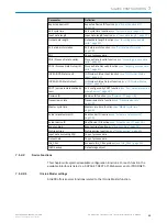
Properties

Value

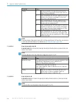
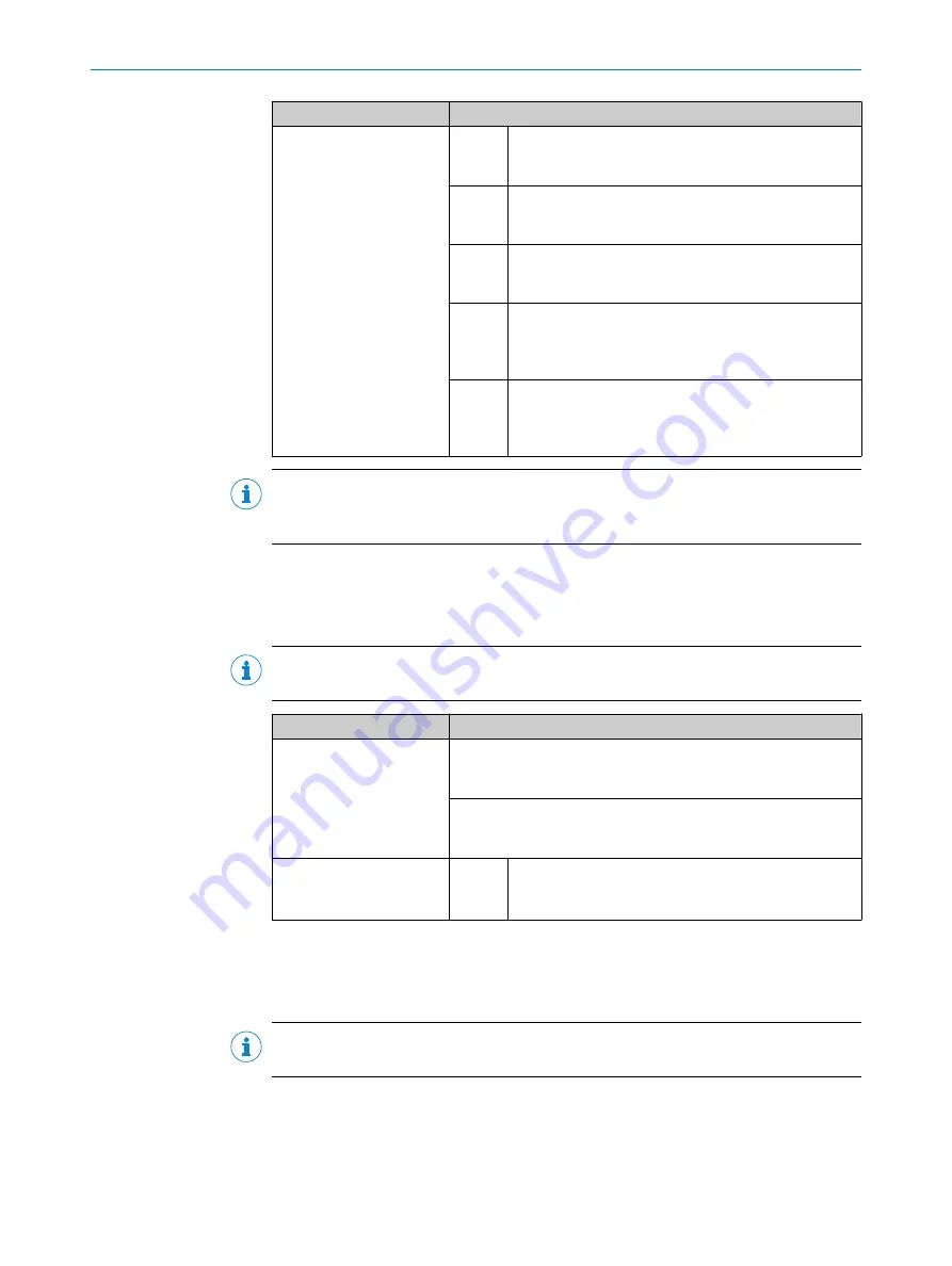
Coding

0

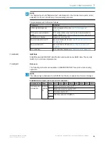
No device inspection: No inspection is performed on
this IO-Link port regarding the correct device ID, manu‐
facturer ID or serial number.

1

Type-compatible device (V1.0): An inspection is only per‐
formed on the IO-Link port with regard to the correct
device ID and manufacturer ID.

2

Type-compatible device (V1.1): An inspection is per‐
formed on the IO-Link port with regard to the revision
ID, device ID and manufacturer ID.

3

Type-compatible device (V1.1) with restore: An
inspection is performed on the IO-Link port with regard
to the revision ID, device ID and manufacturer ID. Data
storage (reading and writing) is permitted.

4

Type-compatible device (V1.1) with restore: An inspec‐
tion is performed on the IO-Link port with regard to the
revision ID, device ID and manufacturer ID. Data storage
(writing) is allowed.

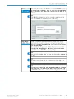
NOTE

For data storage, "Expected Vendor ID" and "Expected Device ID" must be set and must
match the connected device (for details see 

see "Data Storage", page 102

).

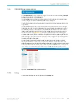
7.1.2.2.1.4

Expected manufacturer ID

Expected Vendor ID

 can be used to specify the vendor ID with which a connected IO-Link

device must match.

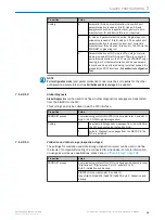
NOTE

The manufacturer ID is only checked at inspection level "1" to "4".

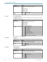
Properties

Value

PROFINET access

Commissioning protocol for all IO-Link device submodules (except
"Digital input", "Digital output"; slot 2, subslot 2 to 5)
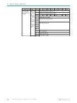
Byte 6 to 7: Expected manufacturer ID

SIG200-IO-Link master (slot 2, subslot 1)
Index 0xB100/0xB101/0xB102/0xB103, byte 6 to 7: Expected
manufacturer ID

Coding

Any

Expected manufacturer ID of the IO-Link device con‐
nected to the IO-Link port (unsigned integer 16)
Example: Manufacturer ID SICK AG = 26

7.1.2.2.1.5

Expected device ID

Expected Device ID

 can be used to specify the device ID with which a connected IO-Link

device must match.

NOTE

The device ID is only checked at inspection level "1 "to "4".

SIG200 CONFIGURATION

36

O P E R A T I N G   I N S T R U C T I O N | Sensor Integration Gateway - SIG200

8017853.1D0S/2021-11-04 | SICK

Subject to change without notice

Summary of Contents for SIG200

Page 1: ...O P E R A T I N G I N S T R U C T I O N Sensor Integration Gateway SIG200 PROFINET Integration Products ...

Page 2: ...f this document is only permissible within the limits of the legal determination of Copyright Law Any modi fication abridgment or translation of this document is prohibited without the express written permission of SICK AG The trademarks stated in this document are the property of their respective owner SICK AG All rights reserved Original document This document is an original document of SICK AG ...

Page 3: ...configuration 13 7 1 SIG200 PROFINET interface 13 7 2 Operation via Webserver 42 7 3 Operation via SOPAS ET USB Ethernet 43 7 4 Configuration via REST API 60 8 Device Functions 102 8 1 Data Storage 102 8 2 Logic Editor 102 9 Troubleshooting 122 10 Disassembly and disposal 123 11 Maintenance 124 12 Technical data 125 12 1 General technical data 125 13 Annex 128 13 1 Conformities and certificates 12...

Page 4: ...rom moisture and contamination These operating instructions contain information required during the life cycle of the gateway CAUTION This equipment is not intended for use in residential environments and may not provide adequate protection to radio reception in such environments 1 2 Notes on UL approval UL Environmental Rating Enclosure type 1 1 SAFETY INFORMATION 4 O P E R A T I N G I N S T R U ...

Page 5: ... atmospheric requirements Operation of the device according to its intended use and enclosure rating IP 67 are only guaranteed if open male and female connectors are sealed with blind plugs If the product is used for any other purpose or modified in any way all warranty claims against SICK AG will be void CORRECT USE 2 8017853 1D0S 2021 11 04 SICK O P E R A T I N G I N S T R U C T I O N Sensor Int...

Page 6: ...IG200 and the connected IO Link devices can be parameterized using the IODD file s The user interface also has a logic editor that can be used to parameterize sensor actuator systems based on the information provided 3 2 Operating and status indicators POWER SF BF C DI DO1 DI C DI DO1 DI C DI DO1 DI C DI DO DI LINK ACT2 LINK ACT1 SF POWER BF DO DI DO DI DO DI DO DI LINK ACT2 LINK ACT1 SIG200 POWER...

Page 7: ...Ö Device in standby no IP address assigned red O Error device not in operation red blinking Ö Warning but device in operation NS Network status dark o No voltage or IP address red green alter nately Ö Self test when switching on green O Valid IP address and CIP connection green blink ing Ö Valid IP address no connection red O IP address assigned to a different device red blinking Ö Connection time...

Page 8: ... on pin 2 Off No additional DI on pin 2 9 C DI DO LED for pin 4 green Pin 4 IO Link commu nication active green blinking Pin 4 no IO Link com munication active 3 PRODUCT DESCRIPTION 8 O P E R A T I N G I N S T R U C T I O N Sensor Integration Gateway SIG200 8017853 1D0S 2021 11 04 SICK Subject to change without notice ...
Page 9: ...not accept the delivery or only do so conditionally Note the scope of damage on the transport documents or on the transport compa ny s delivery note File a complaint NOTE Complaints regarding defects should be filed as soon as these are detected Damage claims are only valid before the applicable complaint deadlines 4 3 Storage Store the device under the following conditions Recommendation Use the ...

Page 10: ...nsure proper ground connection to the housing the coating on the housing around the mounting screws must be removed NOTE There can be several SIG200 mounted side by side without observing a minimum distance between each IO Link Master NOTE There are no blind plugs at ports P1 S1 and Power NOTE There are no screws inlcuded in the scope of delivery 5 MOUNTING 10 O P E R A T I N G I N S T R U C T I O...

Page 11: ...ltage switch on the voltage supply UV 0 V once all electrical connec tions have been established Male and female connectors that are not used must be sealed with blind caps so that the enclosure rating of IP 67 is assured Explanation of the connection diagrams DI Digital input DO Digital output FE functional ground IO Link IO Link communication C n c not connected Rx Receiver Rx Receiver Tx Transm...

Page 12: ...x Receiver 4 3 1 2 Table 5 IO Link Ports S1 S4 M12 A coded Port Class A Pin Signal Description 1 L 24 V DC nominal 2 DI Configurable as Digital Input 3 M 0 V logic ground 4 DI DO or IO Link Configurable as Digital Input or Digital Output or IO Link 5 n c 2 1 5 3 4 6 ELECTRICAL INSTALLATION 12 O P E R A T I N G I N S T R U C T I O N Sensor Integration Gateway SIG200 8017853 1D0S 2021 11 04 SICK Sub...

Page 13: ...face that defines functions for making requests and receiving responses via HTTP protocols such as GET and POST REST Representational State Transfer API Application Programming Interface 7 1 SIG200 PROFINET interface The SIG200 can be parameterized with a suitable PLC and PROFINET software tools This also includes addressing and parameterization The system integration and param eterization describ...

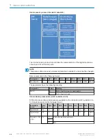
Page 14: ...nk Master the relevant data modules are assigned to a slot or subslot The project planning software represents the data modules broken down according to the slots Within SIG200 the slots are structured in the following way 7 SIG200 CONFIGURATION 14 O P E R A T I N G I N S T R U C T I O N Sensor Integration Gateway SIG200 8017853 1D0S 2021 11 04 SICK Subject to change without notice ...
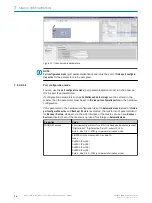
Page 15: ...dard assignment for subslots 2 to 5 in the IO Link master module and subslot 2 of the global function module They must be configured during installation 7 1 1 3 Device Name and PROFINET address The communication parameters of the IO Link Master are displayed by double clicking on SIG200 in the Device overview window SIG200 CONFIGURATION 7 8017853 1D0S 2021 11 04 SICK O P E R A T I N G I N S T R U ...

Page 16: ... be configured Figure 5 PROFINET address Right click on the selected module Then click on Assign device name 7 SIG200 CONFIGURATION 16 O P E R A T I N G I N S T R U C T I O N Sensor Integration Gateway SIG200 8017853 1D0S 2021 11 04 SICK Subject to change without notice ...
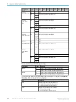
Page 17: ...must correspond to the names previously configured under Properties The identification is done via the MAC address or via the flash test The MAC address is indicated on the label on the side of the SIG200 Figure 7 Device names SIG200 CONFIGURATION 7 8017853 1D0S 2021 11 04 SICK O P E R A T I N G I N S T R U C T I O N Sensor Integration Gateway SIG200 17 Subject to change without notice ...

Page 18: ...in SIO mode use a digital input or digital output module at the corresponding subslot NOTE There is no parameterization for pin 2 Pin 2 is always 0 if there is no physical connec tion If a physical connection exists the signal is automatically transmitted without further parameterization and access can be made via SIG200 IO Link master subslot 2 1 NOTE In order to get valid process data for the lo...

Page 19: ...nload the parameterization Figure 10 Compile 7 1 2 Operation via PROFINET The SIG200 can exchange process data and parameters via PROFINET For this pur pose the IO Link master must be connected to a suitable programmable logic control ler PLC The PROFINET interface of the SIG200 has the following features Properties Values Transmission rate 100 Mbit s Maximum distance between nodes 100 m SIG200 CO...

Page 20: ...33 V2 34 For the integration of the SIG200 into a PROFINET PLC the corresponding GSDML file General Station Description Markup Language must be used Download the GSDML file at www sick com Different versions are available for differ ent engineering tools 7 1 2 1 Device model SIG200 PROFINET represents process data and acyclic data in the following slots The PROFINET slots have the following functi...

Page 21: ...able at the following slots subslots Slot Subslot Designation Function 1 2 Various Data representation in the logic editor 2 1 Pin 2 inputs Acquisition of digital input data at pin 2 of all IO Link ports 2 Various Pin 4 digital input digital output or IO Link data from IO Link port S1 3 Various Pin 4 digital input digital output or IO Link data from IO Link port S2 4 Various Pin 4 digital input di...

Page 22: ...gnation Value Meaning SxDI2 0 Pin 2 of port x is Low or deactivated 1 Pin 2 of port x is High IO Link device process data slot 2 subslots 2 to 5 Different process data submodules are available for IO Link ports slot 2 subslots 2 to 5 Data is presented in the following format Submodule name Direc tion Byte Bit 7 Bit 6 Bit 5 Bit 4 Bit 3 Bit 2 Bit 1 Bit 0 Digital input On 0 0 0 0 0 0 0 0 SxDI1 Digita...

Page 23: ...ta Out 3 IO Link 4I 4O PQI On 0 4 Byte IO Link Process Data In 3 4 PQI Off 0 4 Byte IO Link Process Data Out 3 IO Link 8I 0O PQI On 0 8 Byte IO Link Process Data In 7 8 PQI IO Link 0I 8O PQI On 0 PQI Off 0 8 Byte IO Link Process Data Out 7 IO Link 8I 8O PQI On 0 8 Byte IO Link Process Data In 7 8 PQI Off 0 8 Byte IO Link Process Data Out 7 IO Link 16I 0O PQI On 0 16 Byte IO Link Process Data In 15...

Page 24: ...n Value Meaning SxDI1 0 Pin 4 of port x is Low SIO mode digital input 1 Pin 4 of port x is High SIO mode digital input SxDO1 0 Pin 4 of port x is Low SIO mode digital output 1 Pin 4 of port x is High SIO mode digital output In IO Link mode each IO Link port always has a status byte of input data Port Qualifier Information PQI It contains the following data Bit Description Bit 7 Validity of the dev...

Page 25: ...ster has per formed a data memory upload and a new IOLD backup object 0xB904 is available Logic editor process data slot 1 subslot 2 The following process data submodules are available for the logic editor slot 1 sub slots 2 Submodule name Direc tion Byte Bit 7 Bit 6 Bit 5 Bit 4 Bit 3 Bit 2 Bit 1 Bit 0 Logic editor 2I 0O On 0 2 byte logic editor data input 1 Logic editor 0I 2O Off 0 2 byte logic e...

Page 26: ...7 Logic editor 8I 8O On 0 8 byte logic editor data input 7 Off 0 8 byte logic editor data output 7 Logic editor 16I 0O On 0 16 byte logic editor data input 15 Logic editor 0I 16O Off 0 16 byte logic editor data output 15 Logic editor 16I 16O On 0 16 byte logic editor data input 15 Off 0 16 byte logic editor data output 15 Logic editor 32I 0O On 0 32 byte logic editor data input 31 Logic editor 0I ...

Page 27: ...3 Logic editor 64I 64O On 0 64 byte logic editor data input 63 Off 0 64 byte logic editor data output 63 Logic editor 128I 0O On 0 128 byte logic editor data input 127 Logic editor 0I 128O Off 0 128 byte logic editor data output 127 Logic editor 128I 128O On 0 128 byte logic editor data input 127 Off 0 128 byte logic editor data output 127 SIG200 CONFIGURATION 7 8017853 1D0S 2021 11 04 SICK O P E ...

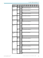
Page 28: ...it 7 Bit 6 Bit 5 Bit 4 Bit 3 Bit 2 Bit 1 Bit 0 Parameteriza tion module Slot 1 subslot 1 8825 0x227 9 0 Recording main version number 1 1 Recording minor version number 0 2 Recording minor version number 0 GDIA G All IO Link device submod ules except Digital input Digital output 47360 0xB90 0 0 Recording main version number 1 1 Recording minor version number 0 4 0 0 0 0 PCM 0 0 5 Validation and ba...

Page 29: ... Port cycle time Port cycle time function see Port cycle time page 37 7 1 2 1 2 2 I M Data SIG200 supports PROFINET identification and maintenance I M data The records I M0 1 2 and 3 are implemented 7 1 2 1 2 3 Data sets The following data sets are available in SIG200 PROFINET for acyclic access during operation NOTE The index range is between 0 and 65535 but there are special and reserved ranges ...

Page 30: ...ain version number 1 1 Block minor version number 0 4 0 0 0 0 PCM 0 0 5 Validation and backup 6 Expected manufacturer ID 7 8 Expected device ID 9 10 11 12 Port cycle time 13 Input data length 14 Output data length 7 SIG200 CONFIGURATION 30 O P E R A T I N G I N S T R U C T I O N Sensor Integration Gateway SIG200 8017853 1D0S 2021 11 04 SICK Subject to change without notice ...

Page 31: ...evice ID 13 14 15 16 Number of event entries 17 Event entry 0 18 19 Event entry N 2 Last event entry N 1 N N 1 Number of profile entries N 2 First profile ID N 3 Second profile ID N M 1 Last profile ID N M IO Link process data 45824 0xB30 0 45825 0xB30 1 45826 0xB30 2 45827 0xB30 3 0 Block main version number 1 1 Block minor version number 0 4 Input data length 5 Input data including PQI N N 1 Out...

Page 32: ... index 0xFE4A 3 4 IOL_CALL controller status 5 IOL_CALL index 6 7 IOL_CALL subindex 8 IOL_CALL data N IOLD backup 47361 0xB90 1 0 Block main version number 1 1 Block minor version number 0 4 Data storage object NOTE The Digital input and Digital output submodules for the IO Link device ports slot 2 subslots 2 to 5 do not have any data sets Data set parameters The parameters for all data sets are d...

Page 33: ...b server page 42 Revision ID Revision ID function see Revision ID page 38 Transmission rate Transmission rate function see Transmission rate page 38 Master cycle time Master cycle time function see Master cycle time page 39 Actual manufacturer ID Real Vendor ID function see Actual manufacturer ID page 39 Actual device ID Real Device ID function see Actual device ID page 39 Event entries Event entr...

Page 34: ...ode instead of IO Link port configuration active and Backup Restore is selected the master is not parameterized for Backup Restore However via the web interface of the master you can see Backup Restore activated even if the master is not used for storage in Automatic mode Properties Value PROFINET access Commissioning protocol for all IO Link device submodules except Digital input Digital output s...

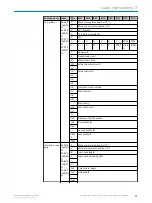
Page 35: ...lobal diagnostics can be used to define whether diagnostic messages are transmitted from the SIG200 to the PLC This setting can only be called up via the PLC interface Properties Value PROFINET access Commissioning protocol SIG200 IO Link master slot 1 subslot 1 Byte 2 bit 1 GDIAG global diagnostics Coding 0 Deactivate All diagnostic messages from the SIG200 to the PLC are deactivated default sett...

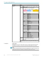
Page 36: ...st be set and must match the connected device for details see see Data Storage page 102 7 1 2 2 1 4 Expected manufacturer ID Expected Vendor ID can be used to specify the vendor ID with which a connected IO Link device must match NOTE The manufacturer ID is only checked at inspection level 1 to 4 Properties Value PROFINET access Commissioning protocol for all IO Link device submodules except Digit...

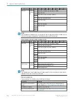
Page 37: ...0xB103 byte 12 Port cycle time Coding 0 As soon as possible 16 1 6 ms 32 3 2 ms 48 4 8 ms 68 8 0 ms 100 20 8 ms 133 40 ms 158 80 ms 183 120 ms 7 1 2 2 1 7 Input data length With Input data length the current input data length can be read out from a provided IODD or determined during startup of the IO Link device NOTE In PROFINET the input data length also contains the PQI byte Port Qualifier Infor...

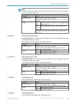
Page 38: ...4 No device on the port 5 Incorrect device on the port 6 Error 255 Information temporarily unavailable 7 1 2 2 1 10 Revision ID Revision ID can be used to read out the IO Link version of the IO Link device on this port Properties Value PROFINET access SIG200 IO Link master slot 2 subslot 1 Index 0xB200 0xB201 0xB202 0xB203 byte 7 Revision ID Coding 16 Version V1 0 17 Version V1 1 7 1 2 2 1 11 Tran...

Page 39: ...onnected IO Link device at this port can be read out Properties Value PROFINET access SIG200 IO Link master slot 2 subslot 1 Index 0xB200 0xB201 0xB202 0xB203 byte 12 to 15 Actual device ID Coding Device ID of the IO Link device connected to the IO Link port unsigned integer 32 7 1 2 2 1 15 Event entries Event entries can be used to read out the number of supported event entries of a connected IO ...

Page 40: ...st available event entry EventCode Event codes are defined by the manufacturer of the IO Link device The following bytes repeat the coding of the first available event entry 7 1 2 2 1 16 Profile entries Profile entries can be used to read out the number of implemented IO Link profiles of a connected IO Link device on this port as well as all profile identification numbers NOTE The byte count for t...

Page 41: ... Incoming process data is invalid 1 Incoming process data is valid 7 1 2 2 1 18 Outgoing process data valid Process Data Out valid can be used to read out whether the current outgoing process data of a specific IO Link port is valid This setting can only be called up via the PLC interface Properties Value PROFINET access SIG200 IO Link master slot 2 subslot 1 Index 0xB200 0xB201 0xB202 0xB203 byte...

Page 42: ...device submodules or the IO Link master submodule IOLM subslot 2 1 CAP The Client Access Point CAP represents the PROFINET data set index that provides the tunnel to the IO Link system The value of this index is 46080 Port Number of the IO Link port on which the function is to be executed 0 to 3 This value is not relevant if IOL_CALL is called via one of the IO Link device submodules since a submo...

Page 43: ... USB or Ethernet NOTE Basically connecting the SIG200 to the computer via Ethernet is recommended When using the USB interface long waiting loading times may occur for large amounts of data as the data transmission rate on the USB interface is limited Especially when saving large data flows in the logic editor there may be connection problems between SOPAS and the device meaning that the logic can...

Page 44: ...ct and on the device Special user levels can be selected via the REGISTER button For the standard configura tion of the SIG200 a special login is not required since the required user levels Run and Maintenance are already stored in the device for details see see User login and editing mode page 49 To parameterize the SIG200 double click on any point on the project icon The device window opens in w...

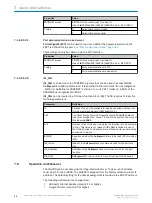
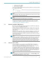
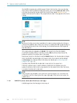
Page 45: ...EDIT button allows the settings on a given configuration page to be changed The EDIT button will be highlighted light blue when pressed Pages that can be configured will be gray until the EDIT mode is activated NOTE 1 Click on the Edit button top right 2 Click the RUN button bottom left 3 Change the operating mode from RUN to MAINTENANCE 4 Insert the password main 5 Now the device parameterization...

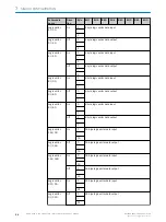
Page 46: ...a button provides the process data of the connected IO Link devices 7 SIG200 CONFIGURATION 46 O P E R A T I N G I N S T R U C T I O N Sensor Integration Gateway SIG200 8017853 1D0S 2021 11 04 SICK Subject to change without notice ...
Page 47: ...firmed again in the Confirm Action field If you click Yes all settings currently stored in the device are overwritten After clicking OK a Success dialog is displayed to confirm the successful reset of the connected SIG200 to the factory settings NOTE While both of the dialogues boxes are active no other interface navigation is possible NOTE The Restore Factory Settings button works from any of the...

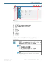
Page 48: ...ed light blue when the device tree is hidden Home Click the Start button at any time to return to the STATUS device page Refresh page Clicking on this button the page contents are refreshed Device informa tion This area on the top left side of the page shows the product name user defined location firmware version and serial number Page contents This area shows the selected page SETTINGS On the SET...

Page 49: ... is activated the last user remains saved even if the parameterization tool SOPAS ET or web browser is closed NOTE Saving the user in a web browser may depend on the cookie settings The following table shows the available users and their initial password Table 11 User Passwords User Initial password Role Run none Read configuration Maintenance main Read and write configuration Please see Settings ...

Page 50: ...switched on The BF bus error LED indicates when there is an error in the PROFINET interface The SF system error LED indicates when there is a system error ACT LINK1 2 indicate if there is Ethernet network connection on either port NOTE Note that the LED displays do not work in real time When the SIG200 is started for the first time the device has an initialization time after switching on of approx...

Page 51: ... IODD Finder and is the preferred method for retrieving the corresponding device IODDs In addition the single IODD can be uploaded as XML file Other settings such as the minimum cycle time or the assignment of port designations can also be made on this page On the IO Link Devices tab there is a page for each IO Link port S1 S4 This tab displays the IODD view device info and parameter data for each...

Page 52: ...slot 1 from the PROFINET configuration stored in the SIG200 In order to guarantee correct process data transfer the expected size should correspond to the selection The structure of the process data can be adjusted according to the application and logic by changing the Input and Output Data Configuration This is important in terms of handling differnet data types in the logic editor The input and ...

Page 53: ...orrect IODD file has been uploaded it can be assigned to the port to which the corresponding device is connected e g port S1 To do this select the IODD file on the right side of the table using the drop down menu All IODDs already in the Repository are displayed and the correct one can be selected If an IODD is to be deleted from the device select the desired IODD and click DELETE After the desire...

Page 54: ...e according to the desired use case If data storage is to be used Expected Device ID and Expected Vendor ID must be set NOTE If an IO Link port has been configured click Apply to change the parameterization Otherwise the parameterization will not be sent to the device NOTE If Fieldbus fieldbus has been configured as the port owner the parameterization is set by the PLC and cannot be changed via th...

Page 55: ...ading all IO Link device data There is no loading information appearing It can happen that the visualization needs 20 s or more untill all parameters are visualized The following figure shows the view in case a corresponding IODD file for an IO Link device was uploaded Figure 19 CONFIGURATION page IO Link devices NOTE The correct IODD file must be uploaded and provided in the device configuration ...

Page 56: ...management of an IO Link devices data storage Upload If the IO Link device is parameterized to Backup Restore this button is used to upload the device parameterization to the local data storage container of the SIG200 If the IO Link device is parameterized to Restore this button deletes the contents of the port data storage container and reinitializes the port 7 SIG200 CONFIGURATION 56 O P E R A T...

Page 57: ...functions to the available input signals and transmit the results to various output signals by dragging and dropping logic blocks and connection cables The left side of the screen lists all configured inputs The upper middle bar contains the available logic gates that can be dragged down into the workspace And listed on the right side are the configured outputs Before setting up any logic it is re...

Page 58: ...nputs A B and not A D The inputs are outlined in red when connections are made to indicate that a connection is still required in this area The two inputs C and D are only active in the logical truth table if a connection has been made NOTE Green input arrows and green text a connection is possible If a connection is not possible the text will have red color and it is not possible to drag a connec...

Page 59: ... reasons changing the original default password is strongly recommended As of firmware version 1 2 0 you are automatically prompted to change the password for the Maintenance user when logging in for the first time If you have changed and forgotten the password please contact SICK service for sup port SIG200 CONFIGURATION 7 8017853 1D0S 2021 11 04 SICK O P E R A T I N G I N S T R U C T I O N Senso...

Page 60: ...ion as an alternative to XML Table 12 Overview Interface see Interface page 72 GET apiversion see GET apiversion page 72 GET openapi see GET openapi page 72 gateway see gateway page 73 GET gateway identification see GET gateway identification page 73 GET gateway capabilities see GET gateway capabilities page 73 GET gateway configuration see GET gateway configuration page 73 POST gateway configurat...

Page 61: ...ee GET devices deviceAlias process data setdata value page 84 POST devices deviceAlias process data value see POST devices deviceAlias process data value page 86 GET devices deviceAlias parame ters index value see GET devices deviceAlias parame ters index value page 86 POST devices deviceAlias parame ters index value see POST devices deviceAlias parame ters index value page 86 GET devices deviceAl...

Page 62: ...ariable Name of the variable to be read or set Method Name of the method to be called QueryParameter Name or combination of names to parameterize the query e g filtering of return data http Host Name api Namespace Name Variable Method NOTE The available variables methods and namespaces are listed below 7 4 3 Requests The SIG200 supports request types GET and POST GET is used to read variables with...

Page 63: ...ariable The variable named angle shall be read Type GET URL http device api angle Payload empty Set variable The variable named angle shall be set to 42 Type POST URL http device api angle MIME Type application json Payload data angle 42 Call method The setDeviceState state method is to be called with a parameter value of 42 Type POST URL http device api setDeviceState MIME Type application json P...

Page 64: ...teed as HTTP requests are based on a standard TCP mechanism When using the web UI or SOPAS ET at the same time the response time increases 7 4 5 Data Types In this chapter each supported Data Type will be discussed Please note that each example is nested inside a JSON object The first value wrapped in double quotes represents the name and the second one the actual value Boolean booleanName true fa...

Page 65: ...er Escaped unicode characters are not supported Enum Enums are numerical types which define a number of values All other values are not permitted and will be excluded enumName ordinal number ordinal number USInt UInt Array An array is an ordered collection of values An array begins with left bracket and ends with right bracket Values are separated by comma arrayName value value value value boolean...

Page 66: ...is should be the preferred method as it ensures compati bility with the device and is also in machine readable format 7 4 6 1 Error messages Table 15 JSON REST general error messages HTTP code Message Description 500 Internal Server Error code 101 message Internal server error NOTE This error can occur with any request code 102 message Internal communication error 404 Not Found code 103 message Op...

Page 67: ...orted 403 Forbidden code 150 message Permission denied NOTE Access is not allowed Check access rights and Port Owner in configu ration This error can occur with any request SIG200 CONFIGURATION 7 8017853 1D0S 2021 11 04 SICK O P E R A T I N G I N S T R U C T I O N Sensor Integration Gateway SIG200 67 Subject to change without notice ...
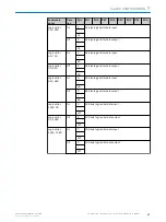
Page 68: ...ata type in the sent JSON object is not correct for example String instead of Integer code 204 message Enumeration value unknown code 205 message JSON data value out of range NOTE The parameter is out of the valid value range Check the correspond ing default code 206 message JSON data value out of bounds NOTE The maximum array string length is exceeded code 207 message deviceAlias is not unique co...

Page 69: ... invalid code 306 message Query parameter value invalid code 307 message Port is not configured to IO Link code 308 message IO Link Device is not accessible code 309 message IO Link parameter not found code 310 message IO Link parameter access not sup ported by the Device code 311 message IO Link parameter access error code 312 message IO Link parameter name is not unique SIG200 CONFIGURATION 7 80...

Page 70: ... Process data error HTTP code Message Description 400 Bad Request code 501 message I Q is not configured as DIGI TAL_OUTPUT code 502 message C Q is not configured as DIGI TAL_OUTPUT code 503 message IO Link device has no output proc ess data 7 SIG200 CONFIGURATION 70 O P E R A T I N G I N S T R U C T I O N Sensor Integration Gateway SIG200 8017853 1D0S 2021 11 04 SICK Subject to change without not...

Page 71: ...nva lid NOTE The uploaded IODD contains XML errors Upload only suitable IODD files code 604 message IODD upload failed CRC error code 605 message IODD upload failed parsing error 500 Internal Server Error code 602 message IODD upload failed not enough memory SIG200 CONFIGURATION 7 8017853 1D0S 2021 11 04 SICK O P E R A T I N G I N S T R U C T I O N Sensor Integration Gateway SIG200 71 Subject to c...

Page 72: ...7 4 6 2 Interface GET apiversion Readout of API version Sample response version V1 0 0 GET openapi Reading of interface in OpenAPI JSON format Sample response openapi 3 0 1 info description This is the description of the SIG200 IO Link Master REST API server version 1 0 0 title SIG200 IO Link Master contact email info sick de license name Apache 2 0 url http www apache org licenses LICENSE 2 0 htm...

Page 73: ...lues are output directly in the appropriate format mqttSup ported Boolean Describes the general support of MQTT Sample response ioddSupported true mqttSupported false GET gateway configuration POST gateway configuration Reading and writing the device configuration or Ethernet settings JSON parameters Type Description ipConfigura tion Enum DHCP MAN UAL Describes the general support for IODD files T...

Page 74: ...are displayed top Integer Filter to output only the first events after switching on the supply voltage bottom Integer Filter to output only the most recent events in time Example of namespace with query parameters http 192 168 2 1 iolink v1 gateway events origin DEVICES deviceA lias master1port1 http 192 168 2 1 iolink v1 gateway events origin ALL bottom 1 http 192 168 2 1 iolink v1 gateway events...

Page 75: ...ice plugged in or igi n portNumber 1 masterNumber 1 POST gateway reboot This command restarts the device and is only acknowledged by the HTTP code 204 POST gateway reset The device is set to the delivery state NOTE By executing the device reset all settings are lost or replaced by the default values SIG200 CONFIGURATION 7 8017853 1D0S 2021 11 04 SICK O P E R A T I N G I N S T R U C T I O N Sensor ...

Page 76: ...dorId 26 deviceId 8389227 http 192 168 2 1 iolink v1 iodds revision 1 1 Sample response vendorId 26 deviceId 8389010 version V1 04 releaseDate 2018 07 17 iolinkRevision 1 1 vendorId 26 deviceId 8389238 version V0 1 releaseDate 2020 11 19 iolinkRevision 1 1 GET iodds file Read out the IODD file specified by the query parameters Vendor and Device ID are required here Namespace example with query par...

Page 77: ...hnology IODD ProfileTechnology ISO15745Reference ProfileHeader ProfileBody POST iodds file Upload and save an IODD file to the device The file must conform to the IODD schema and be in XML format DELETE iodds Delete all IODD files or an IODD file specified by the query parameters Namespace example with query parameters http 192 168 2 1 iolink v1 iodds http 192 168 2 1 iolink v1 iodds deviceId 8389...

Page 78: ...Writing the identification parameters JSON parameters Type Description locationTag String The user can assign a name here that describes the placement of the device in the system 7 4 6 6 Ports GET masters 1 ports Readout of available ports with status information and device pseudonym deviceAlias The portNumber is used to access the individual ports The deviceAlias is used to access the connected I...

Page 79: ...stics of the port Sample response maxPowerSupply value 0 5 unit A portType CLASS A GET masters 1 ports portNumber status Readout of port status JSON parameters Type Description statusInfo Enum DEACTIVATED INCOR RECT_DEVICE DEVICE_START ING DEVICE_ONLINE COMMUNICA TION_LOST DIGI TAL_INPUT_C Q DIGI TAL_OUT PUT_C Q NOT_AVAILA BLE Information about the state of the port Sample response SIG200 CONFIGUR...

Page 80: ...input Digital output Pin 4 is switched as output validatio nAndBackup Enum NO_DEVICE_CH ECK TYPE_COMPATI BLE_DEVICE_V1 0 TYPE_COM PATIBLE_DEVICE_ V1 1 TYPE_COMPATI BLE_DEVICE_V1 1_BACKUP_AND_ RESTORE TYPE_COMPATI BLE_DEVICE_V1 1_RESTORE Configuration options No check Any IO Link devices are detected and proc ess data is transmitted Revision Check This setting activates a check of the IO Link revis...

Page 81: ...sion 1 1 co nte nt DAAAAgAAGAAAAzAxMkAAAAcqKioqKioqWwAAAQBcAAABAHgAAAGB4wAAAQD mAAABAOcAADEAMDAwMDAwMDAwMDAwMDAwMDAwMDAwMDAwMDAwM DAwMDAwMDAwMDAwMDAwMDAwMDAw6AAABwAwMDAAAAClDwACAACnDwD kUEsDBBQACAAIAMkIIeAAAAAAAAAAAAAAAAAAAAAAAAAAAAAAAAACqDwD kAAAAAAAAAAAAAAAAAAAAAAAAAAAAAAAAAAAAAAAAAAAAAAA gAAtA8AAgAAtQ8AAgAAtg8AAgAAtw8AAgAAuA8AAgAAuQ8AAgAAug8AAgAA 7 4 6 7 Devices GET devices Overview of ports an...

Page 82: ...dentification Reading and writing the IO Link device identification data JSON parameters Type Description applica tionSpeci ficTag String The user can assign a name with this parameter which describes the application of the device in the system Refer to the data sheet of the connected IO Link device to see whether the parameter is available locationTag String The user can assign a name with this p...

Page 83: ...equest applicationSpecificTag Test device GET devices deviceAlias events Reading the events of the IO Link device Query parame ters Type Description top Integer Filter to output only the first events after switching on the supply voltage bottom Integer Filter to output only the most recent events in time Sample response time 00 23 21 37 897 severity ERROR message code 4096 mode APPEARS text Genera...

Page 84: ...ttp 192 168 2 1 iolink v1 devices master1port1 processdata value http 192 168 2 1 iolink v1 devices master1port1 processdata set data value format iodd JSON parameters Type Description getData Object Input process data of the connected device setData Object Output process data of the connected device valid Boolean Describes the validity of the process data iqValue Boolean Output state pin 2 cqValu...

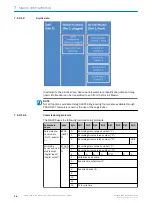
Page 85: ...va lue 0 0 0 0 0 0 0 0 iq Val ue fal se se tDa ta io lin k va lid fal se va lue 0 SIG200 CONFIGURATION 7 8017853 1D0S 2021 11 04 SICK O P E R A T I N G I N S T R U C T I O N Sensor Integration Gateway SIG200 85 Subject to change without notice ...
Page 86: ...ue POST devices deviceAlias parameters index value Reading and writing the IO Link device parameters ISDU http 192 168 2 1 iolink v1 devices master1port1 parameters 24 value value 31 32 33 34 35 GET devices deviceAlias parameters index subindices GET devices deviceAlias parameters index subindices subindex value POST devices deviceAlias parameters index subindices subindex value When reading or wr...

Page 87: ...rameters Output of a list with all parameters contained in the IODD and their names JSON parameters Type Description index Integer Parameter index via which the corresponding ISDU can be accessed parameter Name String Name of the parameter from IODD parameterNa meURI String Name of the parameter without spaces This name is also used to access individual parameters Sample response SIG200 CONFIGURAT...

Page 88: ...parameterNameURI PDInput_Descriptor index 15 parameterName PDOutput Descriptor parameterNameURI PDOutput_Descriptor index 16 parameterName Vendor Name parameterNameURI Vendor_Name index 17 parameterName Vendor Text parameterNameURI Vendor_Text index 18 parameterName Product Name parameterNameURI Product_Name GET devices deviceAlias parameters parameterName value POST devices deviceAlias parameters...

Page 89: ...condition has occurred and no more specific message is suitable Note The Message property may contain more details about the error condition 4 Access denied The request was valid but the server refuses to respond due to an access violation In the event of a variable access it is possible that the variable is defined as read only 5 Not found Variable or method could not be found 6 Out of range The ...

Page 90: ...LocationName GET read header status 0 message Ok data LocationName abc User defined location name of product POST write data LocationName abc api FirmwareVersion GET header status 0 message Ok data FirmwareVersion 1 0 0 0 Firmware version of product api ApplicationVersion GET header status 0 message Ok data ApplicationVersion 1 0 Application ver sion of product api AppEngineVersion GET header stat...

Page 91: ...acturer SICK AG Manufacturer name of product api PowerOnCnt GET header status 0 message Ok data PowerOnCnt 16 Number of power cycles of product api OpHours GET header status 0 message Ok data OpHours 1526 Number of oper ating hours of product api DailyOpHours GET header status 0 message Ok data DailyOpHours 53 687633514 Hours since last start up of prod uct SIG200 CONFIGURATION 7 8017853 1D0S 2021...

Page 92: ...rIPMask 255 255 255 0 Subnet mask of product api EtherIPGateAddress GET header status 0 message Ok data EtherIPGateAddress 0 0 0 0 Gateway address of product api EtherMACAddress GET header status 0 message Ok data EtherMACAddress 0 6 119 0 0 0 MAC address of product 7 SIG200 CONFIGURATION 92 O P E R A T I N G I N S T R U C T I O N Sensor Integration Gateway SIG200 8017853 1D0S 2021 11 04 SICK Subj...

Page 93: ...tion 2 api LabelPort1Pin2 api LabelPort1Pin4 api LabelPort2Pin2 api LabelPort2Pin4 api LabelPort3Pin2 api LabelPort3Pin4 api LabelPort4Pin2 api LabelPort4Pin4 GET header status 0 message Ok data LabelPort1Pin2 abc Reads writes the electronic label for each port pin The maximum length for a label is 8 characters POST write data LabelPort1Pin2 abc api PortOwner1_Fieldbus api PortOwner2_Fieldbus api ...

Page 94: ... crown ac GetDiskUsage POST read header status 0 message Ok data BytesUsed 0 000000 Capacity 2469606195 000000 Returns how many bytes of the device s fil eystem is being used The SIG200 has 3 2GB of availa ble disk space api crown ac GetLinkStatus POST read data Port 1 header status 0 message Ok data Status 100MB Full Duplex Returns the link status of Ether net ports Port 1 or 2 api crown ac GetPo...

Page 95: ... 0 DeviceID 0 Returns the full port configura tion of an IO Link port Port 1 2 3 or 4 api crown ac ReadDataStorage POST read data Port 1 header status 0 message Ok data Returns data storage object as a Base64 coded string of an IO Link port Port 1 2 3 or 4 api crown ac WriteDataStorage POST write data Port 1 DS_Data eHCAIRoA1gGAAAAADAAAA gAAGAAAB3QAdGVzdCB CAAABAkMAAAQAAAACRAAA BAAAAMhRAAAEAAAQA F...

Page 96: ... crown ac SetRestDataIn POST write data Offset 2 Value 1024 Sets a data value as Logic Editor input Offset selects data value Value defines the value api crown ac GetRestDataIn POST read data Offset 0 header status 0 message Ok data Value 1024 Returns a data value that was set as Logic Edi tor input Off set selects data value api crown ac GetRestDataOut POST read data Offset 0 header status 0 mess...

Page 97: ...vailable as a byte array NOTE The available process data index numbers and data format are usually specified by the manufacturer of the IO Link device in the device data sheet Table 26 API version Command HTTP method JSON request part JSON response part Function iolink sickv1 apiversion GET 1 no JSON nota tion Returns the ver sion of the IO Link API The table below lists the access functions in RE...

Page 98: ...ess data out Outgoing process data processDa taIn proc essDataOut Byte array of the process data isValid true false iolink sickv1 writePort process data POST header portNumber 0 data processData Out 0 55 header status 0 message Ok Sets the content of the raw proc ess data outgoing of a connected IO Link device portNumber 0 Port 1 1 Port 2 2 Port 3 3 Port 4 processDa taOut Byte array of the process...

Page 99: ...ce portNumber 0 Port 1 1 Port 2 2 Port 3 3 Port 4 data Empty member for ISDU num ber followed by the byte array of the parameter data NOTE Raw data access is also available when an IODD is assigned Access by name means that data access to the connected IO Link device is extended by metadata Process data is returned segmented and displayed according to the definition in the IODD file ISDU access is...

Page 100: ...rt 4 process Data In Incoming process data out Outgoing process data processDa taIn proc essDataOut Structure of the process data accord ing to IODD isValid true false iolink sickv1 writeDevice process data POST header portNumber 0 data processData Out 0 55 header status 0 message Ok Sets the content of the raw proc ess data outgoing of a connected IO Link device portNumber 0 Port 1 1 Port 2 2 Por...

Page 101: ...ce portNumber 0 Port 1 1 Port 2 2 Port 3 3 Port 4 variable ISDU name specified in the IODD data Struc tured param eter data iolink sickv1 writeDevice ISDU data POST header portNumber 1 data header status 0 message Ok Sets the analyzed parameter data of a connected IO Link device portNumber 0 Port 1 1 Port 2 2 Port 3 3 Port 4 SIG200 CONFIGURATION 7 8017853 1D0S 2021 11 04 SICK O P E R A T I N G I N...

Page 102: ...ver this function only works if the devices are compatible with each other For this reason the Expected Device ID and Expected Vendor ID must also be specified 8 1 1 Example Usage The SIG200 IO Link Master Data Storage functionality allows straightforward replace ment of failed IO Link sensors The following step by step example shows how the SIG200 can be used to commission a new IO Link device so...

Page 103: ... assign the IODDs of the devices to be used in the Logic Editor Removing IODDs of devices which has been connected in the Logic Editor could lead to incompatibilities This is indicated by the following notification Editing Mode Figure 22 Editing Mode 1 To start your configuration change the operating mode from Run to Maintenance because the Run mode is a read only mode 2 Click on Run on the bottom...

Page 104: ...he upper right corner Overview Figure 24 Logic editor screen orange logic blocks green inputs red outputs blue workspace 8 DEVICE FUNCTIONS 104 O P E R A T I N G I N S T R U C T I O N Sensor Integration Gateway SIG200 8017853 1D0S 2021 11 04 SICK Subject to change without notice ...
Page 105: ... individual logic blocks to get more detailed information about their function Figure 26 Logic blocks Use drag drop to select the desired logic block and put it into the workspace To delete logic blocks put them back in the upper area via drag drop The maximum amount of logic blocks which can be used in the logic editor in parallel is 20 blocks DEVICE FUNCTIONS 8 8017853 1D0S 2021 11 04 SICK O P E...

Page 106: ... only two inputs please use always the top two inputs A B and not e g B D Please note whether the values are Integer or Boolean it is only possible to connect Integer with Integer and Boolean with Boolean Boolean values have a black triangle Integer values are easily identifiable by a red triangle Figure 28 Possible connections By clicking on logic block you get information about the possible conn...

Page 107: ...nd outputs Integer Boolean Click on Settings gear to configure parameters and values of the logic block or input output variable Please note that only integer values are allowed 0 65535 NOTE Not all logic blocks are adjustable DEVICE FUNCTIONS 8 8017853 1D0S 2021 11 04 SICK O P E R A T I N G I N S T R U C T I O N Sensor Integration Gateway SIG200 107 Subject to change without notice ...
Page 108: ...ebounceValue Use your mouse to get more information about Logic or DebounceValue Figure 31 Delete connections To remove a connection click on your desired connection and put it in into the garbage bin on the upper area via drag drop 8 DEVICE FUNCTIONS 108 O P E R A T I N G I N S T R U C T I O N Sensor Integration Gateway SIG200 8017853 1D0S 2021 11 04 SICK Subject to change without notice ...
Page 109: ... IODD for the device has been uploaded the process data as they are defined within the IODD of the IO Link device Inputs are displayed on the left side outputs are visualized on the right side of the logic editor workspace So the logic editor view is depending on the connected IO Link devices Example If you connect e g an inductive proximity sensor IMC on port S1 of SIG200 the input side looks lik...

Page 110: ...een configured as Digital Input meaning pin 4 it will be shown on the left side as an input Analog The constant number block can be set to a fixed value to be used for further processing Rest It is possible to set an input value via REST to be processed by the logic configuration of the SIG200 This input will be visualized with Rest In on the logic editor page Profinet The Profinet output block al...

Page 111: ...he Profinet Input block Logics Table 28 Logic blocks Description Addition of the two input values Number of inputs 2 Input data type Integer Input description num1 first input value num2 second input value Number of outputs 1 Output data type Output 1 Identical to input data type Output description result result after addition of the two input values Settings no settings available DEVICE FUNCTIONS...

Page 112: ...o matically reset to the defined start value MANU After reaching the overflow value the counter value can only be reset manually by the setZero or setValue signal Additional information When the maximum counter value overflow value is reached the overflow output is set to High However there is a difference between the automatic and manual modes The automatic mode the value will be set to 0 on next...

Page 113: ...ription Negation of the input value either one s or two s comple ment depending on the configuration Number of inputs 1 Input data type Signed Integer Input description input analog input value Number of outputs 1 Output data type Output 1 Identical to input data type Output description result The one s or two s complement of the input value So the analog output value is the opposite of the input ...

Page 114: ...If 1 bit Input 2 Then Any Input 3 Else Any Input description num1 Boolean input num2 Analog input 1 num3 Analog input 2 Number of outputs 1 Output data type Integer Output description result If num1 is 1 then num2 is forwarded to the result If num1 is 0 then num3 is forwarded to the result false means 0 Settings No settings available Description Clocked rising edge D Flip Flop Number of inputs 2 I...

Page 115: ... input to an analog output Number of input 1 Input data type Float Input description in1 Float value to be converted Number of outputs 2 Output data type analogValue Integer overflow 1 bit Output description analogValue Converted integer value overflow This output is set in case the floating input value exceeds the limitation of integer Settings RoundModes To select if a number should be rounded t...

Page 116: ...escription Conversion of four digital inputs to an analog half byte value Number of inputs 4 Input data type Input 1 16 1 bit Input description in1 first digital input in2 second digital input in4 third digital input in8 fourth digital input Number of outputs 1 Output data type Output 1 Integer or UInteger 8 or 16 bits Output description analogValue analog half byte output value Settings To select...

Page 117: ... 1 High 1 bit Output 2 Time UInteger 32 Output 3 Low 1 bit Output description low This output is active when the time output is lower than LowLimit Information The 1 ms option is not available time This value increments once per TimeBase whenever input is active high This output is active when the time output is higher than the HighLimit Settings EnableMode To activate the mode to specify which ti...

Page 118: ...ll input signals switch within the heartbeat time OutputReset Off Single Dynamic If Output reset Off an Err high and OK low output will stay this way until one of the inputs switches again If Output reset Single Err high and OK low will revert automatically after the Output duration has elapsed and keep this state until a change in the inputs retrigger the heartbeat timer If Output reset Dynamic E...

Page 119: ...h several AND blocks Number of outputs 1 Output data type Identical to input data type Output description level the output depends on the various inputs For more information see truth table Settings No settings available OR Table 30 Thruth table Input A Input B Out put 1 1 1 1 0 1 0 1 1 0 0 0 Description Combine the input signals with a logical OR Number of inputs 4 Input data type 1 bit future ex...

Page 120: ... NAND Table 32 Thruth table Input A Input B Out put 1 1 0 1 0 1 0 1 1 0 0 1 Description Combine the input signals with a logical NAND Number of inputs 4 Input data type 1 bit future extension or n bit Input description levelA first input levelB second input levelC third input levelD fourth input Maximum 4 inputs can be linked together If you want to link more signals you can work with several NAND...

Page 121: ...Number of inputs 2 Input data type 1 bit future extension or n bit Input description levelA first input levelB second input levelC third input levelD fourth input Maximum 4 inputs can be linked together If you want to link more signals you can work with several XNOR blocks Number of outputs 1 Output data type Identical to input data type Output description level the output depends on the various i...

Page 122: ...stem fault dark Device ok green blinking Find Me red blinking System fault of the device LINK ACT 1 Link Activity 1 dark No network connection on port 1 green Network connection on port 1 LINK ACT 2 Link Activity 2 dark No network connection on port 2 green Network connection on port 2 LED Indication Meaning DI LED for pin 2 amber Additional DI on pin 2 off No additional DI on pin 2 C DI DO LED fo...

Page 123: ...nal directives batteries accumulators and electrical or electronic devices must not be disposed of in general waste The owner is obliged by law to return this devices at the end of their life to the respective public collection points This symbol on the product its package or in this document indicates that a product is subject to these regulations DISASSEMBLY AND DISPOSAL 10 8017853 1D0S 2021 11 ...

Page 124: ...he screwed and plugged connections No modifications may be made to devices Subject to change without notice Specified product properties and technical data are not written guarantees 11 MAINTENANCE 124 O P E R A T I N G I N S T R U C T I O N Sensor Integration Gateway SIG200 8017853 1D0S 2021 11 04 SICK Subject to change without notice ...
Page 125: ...S2 S3 S4 P2 P1 9 0 35 38 3 1 51 30 1 28 57 2 24 36 1 42 28 1 1 198 5 7 81 213 9 8 42 1 4 3 2 PROFINET Figure 33 Dimensional drawing Housing material Zinc Enclosure rating per IEC 60529 IP 67 only when plugged in and threaded in 1 Dimensions W x H x D 213 9 x 38 3 x 57 mm Mounting type Mounting slots front and side Weight 520 g 1 If cables are not plugged in the connector caps supplied with the dev...

Page 126: ...to be limited 2 Max port current includes both the digital current output Pin 4 and the connected device s current consumption Pin 1 3 Pin 4 configured as digital output Maximum output supply current is independent of Pin 1 PROFINET PROFINET IP port 1x10 Nase 100 Base Tx Line type according to IEEE 802 3 Min STP CAT 5 ST CAT 5e Data transmission rate 10 100 Mbits s Max distance between nodes 100 m...

Page 127: ...e for 150 kB file size Max number of I Os which can be connected 52 I Os together with 4 SIG100 Max number of IO Link signals which can be connected 4 Ethernet Ports 2 Max Output frequency 35 Hz12 1 With basic logic not gate logic 2 Max frequency will vary depending on logic configuration IO Link Specification V1 1 Port Class A Transfer rate COM1 COM2 COM3 Min IO Link cycle time 1 ms Input specifi...

Page 128: ... instructions for the product at www sick com To do so enter the product part number in the search field part number see the entry in the P N or Ident no field on the type label 13 ANNEX 128 O P E R A T I N G I N S T R U C T I O N Sensor Integration Gateway SIG200 8017853 1D0S 2021 11 04 SICK Subject to change without notice ...
Page 129: ...ANNEX 13 8017853 1D0S 2021 11 04 SICK O P E R A T I N G I N S T R U C T I O N Sensor Integration Gateway SIG200 129 Subject to change without notice ...
Page 130: ...8080 7425 E Mail enquiry my sick com Mexico Phone 52 472 748 9451 E Mail mexico sick com Netherlands Phone 31 0 30 229 25 44 E Mail info sick nl New Zealand Phone 64 9 415 0459 0800 222 278 tollfree E Mail sales sick co nz Norway Phone 47 67 81 50 00 E Mail sick sick no Poland Phone 48 22 539 41 00 E Mail info sick pl Romania Phone 40 356 17 11 20 E Mail office sick ro Russia Phone 7 495 283 09 90...

Reviews: