2
SICK system
3
Data cable (Ethernet)
4
Data output
5
Client computer
6
Customer interface (connection optional)
5.3
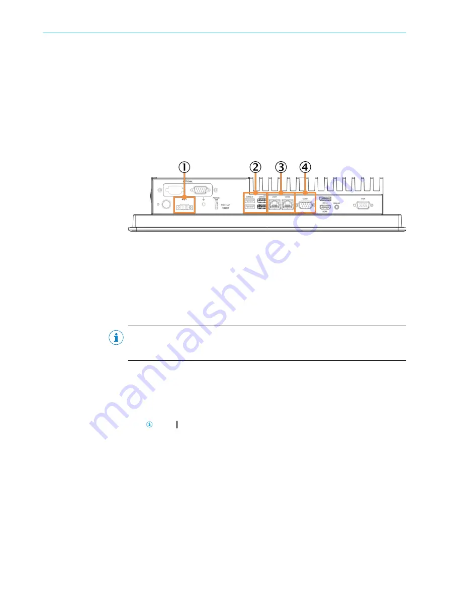
Relevant connections on the device
Overview
The following connections are relevant for integrating the device into the SICK system.
Figure 3: Relevant connections on the rear of the panel PC
1
Voltage supply
2
USB connections
3
Ethernet ports: Connection
•
to the customer interface for accessing the panel PC via the customer network
•
of the data cable for integrating the panel PC into the SICK system
•
of the configuration PC
4
COM1 for RS232/422/485
NOTE
A description of all the connections on the device can be found in the manufacturer’s
operating instructions.
5.4
Connecting the voltage supply
The following connection variants are possible:
•
Connecting the device to the mains supply
This variant is suitable when expanding a SICK system with an industrial PC.
NOTE
The socket must be provided by the customer at the installation loca‐
tion.
•
Connecting the device to the fuse module in the control cabinet
This variant is particularly suitable for use when setting up a new SICK system and
it is planned to integrate an industrial PC.
ELECTRICAL INSTALLATION
5
8027793/V1-0/2022-07-01 | SICK
O P E R A T I N G I N S T R U C T I O N S | SID Pro
15
Subject to change without notice


