2
OSSDs of safety laser scanner
4.5.1.3
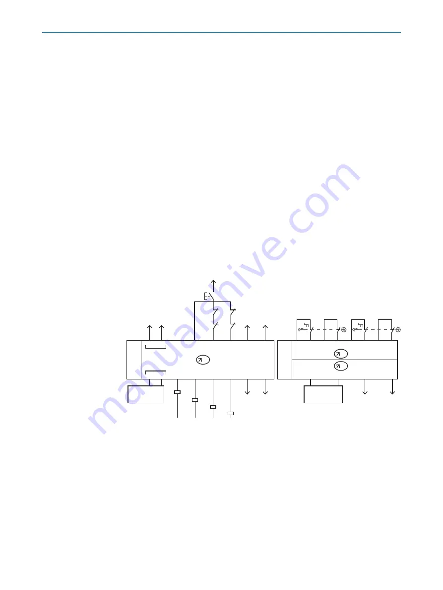
Circuit diagram for automated reset
In order to configure the logic for the safety system, this must be set with the rotary
switch of the Flexi Classic safety controller.
Program 8 must be selected on the UE410-MU.
Program 3 must be selected for channel A on the UE410-8DI and program 6 for chan‐
nel B.
Q3 and Q4 switch depending on the status of the primary protective device and safety
laser scanner used (channel B).
Q1 and Q2 switch depending on the status of the emergency stop pushbutton (channel
A).
The normally open contacts of the relays at Q3 and Q4 must have a dual-channel con‐
nection to the protective stop input in the robot controller.
For automated reset and EDM, the normally closed contacts must be connected in
series on S2.
The normally open contacts of the relays at Q1 and Q2 must have a dual-channel con‐
nection to the emergency stop input in the robot controller.
For manual reset and EDM, the normally closed contacts must be connected in series
with the reset pushbutton on S1.
+24V
Reset
-K1
-K2
-K3
-K4
-K3
-K4
-K1
-K2
+24V
+24V
+24V +24V
S3
A1
S1
S2
X1
X2
I1
I2
EN
A2
+24V
+24V
+24V
OV
Q3
Q4
OV
OV
OV
OV
Q1
Q2
I3
A
B
A
B
MU
8DI
8
3
6
I4
X4
I4
X3
I3
X2
I2
X1
I2
X8
I8
X7
I7
X6
I6
X5
I5
1
2
Figure 13: Circuit diagram for automated reset
1
OSSDs of primary protective device (e.g. safety light curtain)
2
OSSDs of safety laser scanner
4.5.1.4
Circuit diagram for automated reset with UE410-4RO
A more detailed description is provided by the supplied circuit diagram (PDF).
4
PROJECT PLANNING
34
O P E R A T I N G I N S T R U C T I O N S | sBot Stop
8023421/12KF/2019-01-22 | SICK
Subject to change without notice


