background image

These measures must be selected in the SISTEMA project file for each user-defined
subsystem. In addition, the correct values must be chosen for those components that
are not part of the scope of delivery

see "General requirements", page 30

.

4.4

Design

This chapter contains information about implementing the design of the functional
safety system. Any design-related contents of the relevant operating instructions also
apply. The following information is provided in the operating instructions for safety laser
scanners in particular:

Height of the scan plane

Protective field length

Protective field width

Stopping distance

Monitoring case switching time

4.4.1

Safety laser scanner

It is recommended to mount the safety laser scanner horizontally so that the scan
plane is 300 mm above the ground. This means a resolution of 70 mm can be used.

If the mounting height is less than 300 mm above the ground, the resolution must be
adjusted to 50 mm and the protective field must be enlarged.

NOTE

At a resolution of 50 mm, the maximum size of the protective field is reduced. The man‐
ufacturer must ensure that there is no possibility of avoiding the protective field.
If the height of the scan plane is greater than 300 mm, additional measures must be
taken to prevent crawling beneath.

4.4.2

Robot operating modes

Implementation of operating modes and the operating modes considered

Selecting between the robot operating modes is not a part of this safety system. You
must select the operating mode using the robot controller (e.g. with the operating mode
selector switch in the robot operating panel).

This safety system takes the following operating modes into account:

Automatic

Manual operating mode with reduced speed

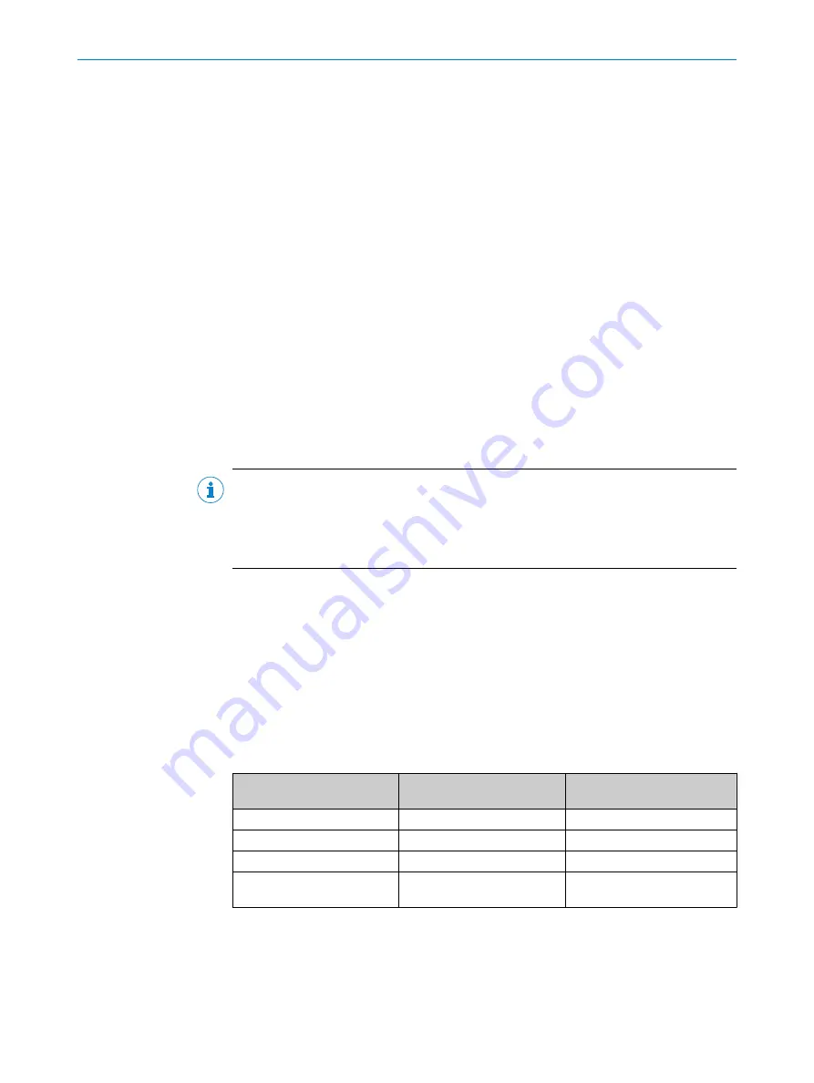
Table 13: Functional scope depending on the selected operating mode

Function

Automatic operating mode

Manual operating mode with
reduced speed

Emergency stop

Active

Active

Safety-rated monitored speed Active

Not active

Initiate a protective stop

Active

Not active

Automatic mode stop (SAFF
safeguarding fence)

Active

Not active

Complementary information

You must configure the robot controller for the manual operating mode so that sig‐
nals for a protective stop and safety-rated monitored speed can be bridged.

Each time the user mode is changed, the safety system must be manually reset.

PROJECT PLANNING

22

O P E R A T I N G   I N S T R U C T I O N S | sBot Speed – YA

8024620/16AH/2019-12-02 | SICK

Subject to change without notice

Summary of Contents for sBot Speed - YA

Page 1: ...O P E R A T I N G I N S T R U C T I O N S sBot Speed YA Safety System...

Page 2: ...ble within the limits of the legal determination of Copyright Law Any modifica tion abridgment or translation of this document is prohibited without the express writ ten permission of SICK AG The trad...

Page 3: ...tions 15 3 5 Additional components required 18 3 5 1 Emergency stop pushbutton requirements 19 3 5 2 Reset pushbutton requirements 19 3 5 3 Indicator light requirements 19 3 5 4 Robot controller requi...

Page 4: ...ses 37 7 5 5 Verification of the logics 38 7 5 6 Linking outputs and logic 38 7 5 7 Content of the logic editor 38 7 6 Configuring the safety laser scanner 43 7 6 1 Pre configured project file 43 7 6...

Page 5: ...s Safety controller 60 15 Accessories 61 15 1 Connectivity 61 15 2 Mounting bracket 61 15 3 Emergency stop and reset pushbutton 61 16 Annex 62 16 1 Checklist for initial commissioning and commissionin...

Page 6: ...rt number Operating instructions microScan3 Core I O 8016344 Operating instructions Flexi Soft modular safety con troller hardware 8012999 Operating instructions Flexi Soft in the Flexi Soft Designer...

Page 7: ...a situation presenting possible danger which may lead to property damage if not prevented NOTE Indicates useful tips and recommendations Instructions to action b The arrow denotes instructions to acti...

Page 8: ...ing requirements must be met The supplied Flexi Soft file and the SISTEMA file must be adjusted to the individual application in accordance with the manufacturer s requirements Additional protective d...

Page 9: ...lanning a person is considered competent when he she has expertise and experience in the selection and use of protective devices on machines and is familiar with the relevant technical rules and natio...

Page 10: ...is initiated in the following cases Protective field infringed Emergency stop pushbutton actuated Fields are not infringed in an expected sequence sequence error no safety func tion Connection betwee...

Page 11: ...n order to reduce the risk of injuries caused by the movement of the robot while also increasing productivity Figure 1 Example application The industrial robot system consists of the following compone...

Page 12: ...d manual restart can be implemented instead If a person does not leave the hazardous area in the intended manner the safety sys tem prevents a restart Regardless of how the automatic restart is implem...

Page 13: ...ented automated restart occurs once the entire hazardous area of the safety laser scanner is monitored and the sequence for leaving the hazardous area has been carried out correctly Additional functio...

Page 14: ...ield The protective field protects the hazardous area immediately surrounding the robot If the protective field is interrupted the robot is stopped 3 4 2 Field set The safety system provides two field...

Page 15: ...ld set 1 warning field 1 protective field 1 large Field set 2 warning field 2 protective field 2 small 3 4 3 1 1 Approaching the hazardous area Figure 6 Switch field sets If the warning field is infri...

Page 16: ...et 1 when the warning field is clear 4 Once protective field 1 and the warning field are clear the robot may resume work at maximum speed Safe distance protective field from field set 1 and the warnin...

Page 17: ...safety laser scanner at all times The restart remains locked until the person has completely and safely exited the hazardous area while maintaining the minimum distance If these requirements are fulfi...

Page 18: ...te is to be maintained until a man ual reset device is activated and the machine can subsequently be restarted This safety function consists of the following sub functions Start up due to an internal...

Page 19: ...he emergency stop pushbuttons must be designed in accordance with the following standards ISO 13850 IEC 60204 3 5 2 Reset pushbutton requirements The reset pushbutton must be installed outside of the...

Page 20: ...rt after a change in the operating mode e g from automated teach in mode A restart is only possible after a valid reset After protective stop The safety system automatically resets and switches the sa...

Page 21: ...ng duties b Executing a risk assessment b Verifying and validating the safety functions b Integrating the individual components in accordance with the appropriate stan dards b Compliance with the appl...

Page 22: ...ibility of avoiding the protective field If the height of the scan plane is greater than 300 mm additional measures must be taken to prevent crawling beneath 4 4 2 Robot operating modes Implementation...

Page 23: ...safety system tR Robot stopping time tRobot Supplements Supplement to prevent reaching over CRO Supplement for the maximum sensing range of the robot arm CRobot Supplement for the distance between th...

Page 24: ...chine tR Response time of safety system tRobot Robot stopping run down time CRO Supplement to prevent reaching over 1 200 mm 0 4 H CRobot Maximum sensing range of the robot CTool Distance between the...

Page 25: ...utside the hazardous area and outside the warning field of the safety laser scanner For more information see Reset pushbutton requirements page 19 4 5 Integrating the equipment into the electrical con...

Page 26: ...troller via the safety relay The safety system can therefore be used on a robot controller with test pulse output or with complementary equivalent inputs Examples 24 V 0 V 3 4 1 2 Figure 10 Circuit wi...

Page 27: ...ty function Must be configured in robot controller SPEED LIMIT Automatic mode stop SAFF safeguarding fence Module 5 33 34 43 44 The enabling current paths are switched by safety output Q4 module 2 SAF...

Page 28: ...ponents of the safety system see operating instructions of the components In many cases depending on the application conditions the risk assessment can determine that further thorough checks are requi...

Page 29: ...mmended values Table 16 microScan3 Core I O recommended values Height of scan plane 300 mm Resolution 70 mm NOTE If the height of the scan plane is less than 300 mm then a resolution of 50 mm must be...

Page 30: ...ction against overvoltage overcurrent etc per the manufacturer instructions for the individual components Mechanical fastening of the wiring of the pushbutton for the hold to run device e g with cable...

Page 31: ...cy stop l6 Module 4 Y4 EDM protective stop l7 Module 5 Y2 Safety rated monitored speed EDM I8 Module 5 Y4 EDM automatic mode stop SAFF safeguarding fence Table 19 Module 2 outputs Terminal Connect to...

Page 32: ...rated moni tored speed 23 24 Terminal strip X181 7 8 XD2 21 19 Safety rated moni tored speed 33 34 Terminal strip X18 1 2 XD1 33 31 Automatic mode stop SAFF safeguarding fence 43 44 Terminal strip X1...

Page 33: ...fety Designer 8018178 Approach 1 Download and open configuration file 2 Set application specific parameters 3 Complete configuration 4 Transfer configuration to the safety controller 5 Verify and vali...

Page 34: ...red export file 2 Click on Hardware configuration 3 In the Info selection window click on info 4 Make sure that the checksum that is displayed corresponds to one of the following checksums Table 27 Ch...

Page 35: ...ld Set 2 active Field becomes free Field is infringed PF Protective field WF Warning field Operation speed Robot executes tasks at normal speed Monitored speed Robot executes tasks at safety rated mon...

Page 36: ...F1 free Increase speed End Time delay Figure 12 Logic of the project file person stands next to robot Process when a person passes by the robot Start Worker passes by WF infringed Ac vate Safety rated...

Page 37: ...anchor points which represent the inputs and outputs of the elements A link can only be created between the anchor point on the right side of an element and the anchor point on the left side of anoth...

Page 38: ...ety controller b Check whether the logics in the safety requirements of the application are suffi cient before outputs of the function blocks are linked to outputs of the safety con troller The manufa...

Page 39: ...after the safety rated monitored speed has been activated 7 5 7 2 EmergencyStop page This page is used to configure the logic for the emergency stop The emergency stop must be manually reset from a p...

Page 40: ...Stop page This page is used to configure the logic for the protective stop The ProtectiveStop output is High if the protective field is free and the emergency stop is not triggered In order to avoid a...

Page 41: ...t and must be defined by the manufac turer see Approaching the hazardous area page 15 If the warning field clears rising signal edge then the MonitoredSpeedActive signal is immediately set to Low allo...

Page 42: ...ed to configure the logic for sequence monitoring The sequence check should prevent an unexpected restart if there is misuse or if a per son has not left the hazardous area via the intended route For...

Page 43: ...ls in the AND function block with the safety signal 7 5 7 7 ErrorHandling page This page is used to configure the logic for error rectification If the defined sequence is not complied with the ErrorLE...

Page 44: ...microScan3 Core I O configuration overview Resolution 70 mm NOTE The height of the scan plane must be checked see Mounting the safety laser scan ner page 29 7 CONFIGURATION 44 O P E R A T I N G I N S...

Page 45: ...on overview Configuring the large protective field Figure 19 microScan3 Core I O configuration overview CONFIGURATION 7 8024620 16AH 2019 12 02 SICK O P E R A T I N G I N S T R U C T I O N S sBot Spee...

Page 46: ...O 1 pin 5 and must be set to high by default blue line in the square in the pin description The static control input signal is complementary input A at Uni I O 2 and Uni I O 3 for switching field sets...

Page 47: ...es of the robot b Bear in mind that someone may already be in the protective field at the point when the monitoring cases switch Only switching in time namely before the dan ger arises for the person...

Page 48: ...Enter the password if necessary Configure SAFETY LOGIC CIRCUIT 5 Select SAFETY FUNC in the main menu 6 Select SAFETY LOGIC CIRCUIT 7 Press PAGE on the hand held programming device 8 Configure the saf...

Page 49: ...STOP FILE VALID CON SIGNAL CTRL GROUP R1 1 LIMIT SPEED 0 0 mm sec DETECTION DELAY TIME 1 00 sec 1 2 ACCEP RNG 2 000 mm 1 3 INPUT SIGNAL bit0 FSBIN01 1 ON bit1 MS OUT01 OFF bit2 MS OUT02 ON 1 Example v...

Page 50: ...Prerequisites The SAFETY MODE is active SYSTEM INFO SECURITY SAFETY MODE Approach Configuring the condition file for safety rated monitored speed 1 Select a free condition file 2 Perform the followin...

Page 51: ...of the safety con troller see SafetyRatedMonitoredSpeed page page 41 Example 3 Press WRITE The Update the file dialog box appears 4 Press YES Check safety logic and condition file 5 Warning field infr...

Page 52: ...ounting or the electrical connection After exceptional events such as after a manipulation has been detected after modification of the machine or after replacing components The thorough check ensures...

Page 53: ...omponents 9 1 Start sequence after start up 1 Ensure that the protective field and warning field are clear 2 Press the reset button Robot can start OPERATING THE COMPONENTS 9 8024620 16AH 2019 12 02 S...

Page 54: ...rated according to their specifications Safety features must be regularly checked for reliability NOTE Safety devices must not be disassembled modified or repaired Doing so could other wise impair the...

Page 55: ...er scanner Safety signs information labels b Regularly check the information labels for the following points Presence Readability b Replace the information labels if missing damaged or illegible MAINT...

Page 56: ...and requires a manual reset The output Q4 ErrorLED of the XTIO module 2 can be used to diagnose the status of the sequence monitoring If the EXT_SAFF_OK signal is faulty the Q4 output is continuously...

Page 57: ...etermined using the following formula tR tS tFlexiSoft tRelays Table 33 Variables in the calculation Formula symbols Relevance tR Response time of safety system tS Response time of the microScan3 Core...

Page 58: ...Meaning tO Time for processing and output of the microScan3 Core I O 10 ms 12 TECHNICAL DATA 58 O P E R A T I N G I N S T R U C T I O N S sBot Speed YA 8024620 16AH 2019 12 02 SICK Subject to change...

Page 59: ...module UE410 safety controller 13 2 Ordering information Table 35 sBot Speed hardware ordering information Description Part number Safety system sBot Speed hardware package 1106014 Table 36 Software...

Page 60: ...2 Order Details Safety controller Table 38 Order Details Safety controller Num ber Name Description Part number 1 FX3 CPU000000 Flexi Soft main module FX3 CPU0 1043783 1 FX3 MPL000001 System plug for...

Page 61: ...74 Male connector USB A straight mini USB 3 m cable Configuration of the microScan3 Core I O safety laser scanner 6042517 15 2 Mounting bracket microScan3 Core I O Part Part number Mounting kit 1b For...

Page 62: ...art up safety function Test sequence Expected result Result OK 1 Press Emergency stop pushbut ton 2 Unlock the emergency stop push button 3 Check whether the emergency stop pushbutton is installed out...

Page 63: ...ning field of the safety laser scanner The robot reduces its speed and after the configured delay time the smaller protective field is active The robot remains still until the warn ing field and prote...

Page 64: ...can ner is in correct proportion to the height of the scan plane It is not possible to walk behind the protective field Yes No Test for automatic restart Table 47 Test for automatic restart Test seque...

Page 65: ...s fence screen etc are installed in such a way as to prevent their removal or tampering Yes No Protective devices are protected against manipulation Yes No Protective devices are installed in such a w...

Page 66: ...1 KF111 I8 EDM B4 Actuators BG210 KF112 Q1 microScan3 Core I O Uni I O 2 BG210 KF112 Q2 microScan3 Core I O Uni I O 3 SF300 KF112 Q3 Reset required KF300 KF111 Q1 B1 E Stop KF300 KF111 Q2 B2 protectiv...

Page 67: ...ANNEX 16 8024620 16AH 2019 12 02 SICK O P E R A T I N G I N S T R U C T I O N S sBot Speed YA 67 Subject to change without notice...

Page 68: ...080 7425 E Mail enquiry my sick com Mexico Phone 52 472 748 9451 E Mail mexico sick com Netherlands Phone 31 0 30 229 25 44 E Mail info sick nl New Zealand Phone 64 9 415 0459 0800 222 278 tollfree E...

Reviews: