


Operating Instructions
Chapter
6
RFH620 Interrogator
Electrical installation
8013105/0000/2009-05-12
©
SICK AG · Division Auto Ident · Germany · All rights reserved
43
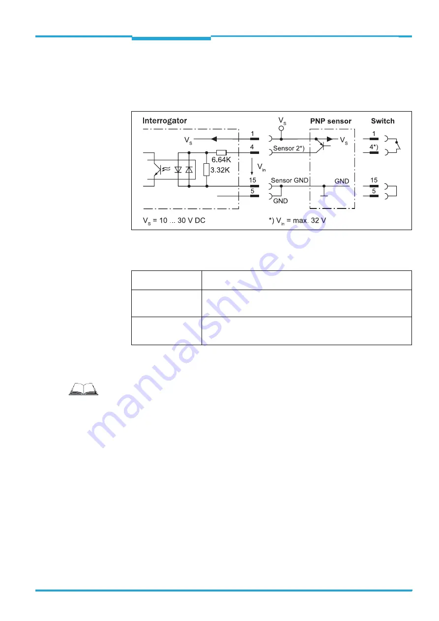
The "
sensor 2
" switching input has the following functions, among others:
Trigger source for
•
Reading pulse generator for reading pulse end
Fig. 6-5:
Wiring "sensor 2" switching input on the 15-pole D-Sub-HD plug
Important
The ratings for "sensor 1" and "sensor 2" are identical.
Tab. 6-7:
Ratings for the switching inputs
>
Connect switching inputs depending on application.
Switching behaviour
Power fed to the input opens the internal reading gate of the interrogator.
(Default setting: active high, debouncing: max. 30 ms (standard))
Features
– Optodecoupled, reverse polarity protected
– Can be wired with the PNP output of a sensor
– Switching input has no hysteresis
Electrical values
Low: |U
e
|
≤
2 V; |I
e
|
≤
0.3 mA
High: 6 V
≤
|V
e
|
≤
32 V; 0.7 mA
≤
|I
e
|
≤
5 mA
Signal threshold > 3.9 V
Important
To wire the switching inputs using connection module CDB620 or CDM420, see operating
instructions "Connection Module CDB620" (no. 8012119, German/English edition) and
"Connection Module CDM420" (no. 8010004, German/English edition) respectively.