


Operating Instructions
Chapter
4
RFH620 Interrogator
Product description
8013105/0000/2009-05-12
©
SICK AG · Division Auto Ident · Germany · All rights reserved
25
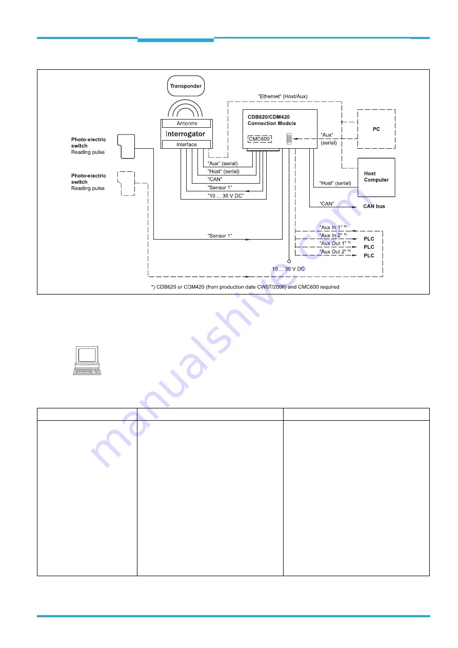
Fig. 4-5:
Ethernet version: Electrical connections to the interrogator with plug connector unit
The detailed wiring of the interrogator and the connections to the host/PC and to the exter-
nal sensors is described in
chapter 6 Electrical installation, page 35
.
Note
Among other things, the following functions can be configured using the SOPAS-ET configu-
ration software:
Function
Description
Configuration with SOPAS-ET
Object trigger control
In order to start an object-related reading pro-
cess, the interrogator requires an appropriate
external signal (trigger source) for reporting an
object in the reading area. As standard, the start
signal is emitted via an external reading pulse
sensor (e. g. photoelectric reflex switch). As soon
as an object has passed the reading pulse sen-
sor, a time window opens in the interrogator
("reading gate") for the reading process.
Alternatively, a command activates the reading
process via a data interface or the CAN-SENSOR
network. In Automatic Cycle mode, the actual
interrogator generates the reading gate inter-
nally with an adjustable mark-space ratio.
The reading pulse can be ended in a number of
ways: With external triggering by the reading
pulse source or a command, internally by a timer
or an evaluation condition to be met.
P
ROJECT
TREE
,
RFH620
,
PARAMETER
,
O
BJECT
TRIGGER
CONTROL