
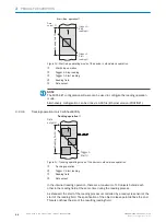


4
Reading window on side
5
Supervision
6
Side view
7
Middle position 105° = default
5.4.5
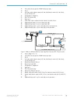
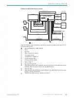
Count direction of the reading angle and the code angle
The device can scan and decode several bar codes at each reading.
At the same time, the location-specific reading diagnostics data are determined for
each of them.
■
The reading angle, starting from the reading window, at which the device detects
the bar code center on the red scanning line of the deflected scanning beam can
be outputted as an RA (reading angle) value.
■
In addition, in the device with oscillating mirror, the angle of deflection of the scan
line under which the device detects the bar code on the red scan line can be
released as the CA (code angle) value.
By determining the RA/CW value, identical bar codes (code type, code length, and data
content) can be separated, and the bar code data can be assigned based on its posi‐
tion on the object.
Line or raster scanner
1
Line or raster scanner
1
Line scanner with oscillating mirror
2
(front reading window
3
)
(side reading window
4
)
(side reading window
4
)
Figure 19: Counting direction of the reading angle RA in the scanning line and of the angle of
deflection CW of the scanning line
1
Line or grid scanner
2
Line scanner with oscillating mirror
3
Reading window on front
4
Reading window on side
Resolution of the reading diagnostic data:
•
Reading angle
α
(aperture angle) in scanning direction: 1° = 2 RA (50° = 100 RA)
•
Angle of deflection of scanning line across scanning direction: 1° = 2 CW (20° =
40 CW)
MOUNTING
5
8019588/129Z/2019-02-07 | SICK
O P E R A T I N G I N S T R U C T I O N S | CLV63x, CLV64x, CLV65x
33
Subject to change without notice


