Commissioning Instructions 8013512
Jan 2005
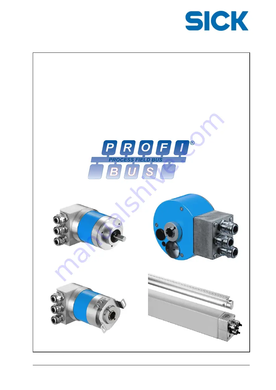
Commissioning Instructions
ATM60 / ATM90 / KHK53
with Profibus DP Interface to EN 50170 Vol. 2
SICK AG
Erwin-Sick-Str. 1 ·
D-79183 Waldkirch
Page 1: ...Commissioning Instructions 8013512 Jan 2005 Commissioning Instructions ATM60 ATM90 KHK53 with Profibus DP Interface to EN 50170 Vol 2 SICK AG Erwin Sick Str 1 D 79183 Waldkirch ...
Page 2: ...icated or passed to third parties without the agreement of SICK AG The data in this documentation describes the product The properties however are not guaranteed SICK AG Erwin Sick Str 1 D 79183 Waldkirch www sick com info sick de Version We reserve the right to make technical changes to the documentation and the products at any time Dec 2021 ...
Page 3: ...ibus Standardisation 14 4 2 Profibus DP 14 4 2 1 DP V0 Communication Protocol 15 4 3 Physical Profibus Network Link 16 4 3 1 Network Topology 16 4 3 2 RS485 Transmission Technology 17 4 3 3 Installation Notes re RS485 17 4 3 4 Profibus Cabling for RS485 18 4 3 5 Cable Screening 19 4 4 Device Profiles 19 4 5 Further Information 20 5 Encoder Modes 21 5 1 Cyclical Data Transmission 21 5 1 1 Parameter...
Page 4: ...rametrisation 37 8 3 1 DP Specific Standard Data 37 8 3 2 Device Specific Data 38 8 3 3 Operating Mode 38 8 3 3 1 Code Sequence 38 8 3 3 2 Class 2 Functionality 39 8 3 3 3 Commissioning Diagnostics Control 39 8 3 3 4 Scaling Function 39 8 3 3 5 Enabling the SSA Service 39 8 3 3 6 Selection of the Address Setting 39 8 3 4 Measuring Units per Revolution CPR 40 8 3 5 Total Measuring Range CMR 40 8 4 ...
Page 5: ...r Revolution CPR 52 9 5 12 Number of counts per Measuring Range CMR 53 9 5 13 Serial Number 53 9 6 Manufacturer Specific Diagnostics Manufacturer Class 53 9 6 1 Station Address 53 9 6 2 Encoder Status 53 9 6 3 DP Controller Status 54 10 Encoder Mounting and Connection 55 10 1 Mounting 55 10 2 Screening 55 10 2 1 Screen Connection at the Bus Link Adapter with Cable Fitting ATM60 P ATM90 P KHK53 P 5...
Page 6: ...Information 67 11 Technical Description 68 11 1 Description of the Rotary Encoders 68 11 2 Description of the Linear Encoder 68 11 3 Profibus Interface Brief Overview of Specific Features 68 11 4 Profibus Interface Specification 69 List of Figures 70 Notes 71 ...
Page 7: ...Dec 2021 ATM60 ATM90 KHK53 5 ...
Page 8: ... edition New information N New properties and additional information on existing properties Revised information R Revisions to the previous edition which require a different procedure during commissioning Inf Revisions Chapter Rev Date First edition of the document 1 00 Jan 2005 Change of address and addition of UK Declaration of Conformity 1 00 Dec 2021 ...
Page 9: ...dge of applicable safety regulations 1 2 Documentation The complete documentation comprises of Commissioning Instructions ATM60 ATM90 KHK53 with Profibus DP Interface Assembly instructions for the particular encoder Device master file GSD GSE This documentation 1 3 Definition of the Symbols Used in the Document This symbol identifies text which must be given special attention to ensure cor rect us...
Page 10: ...Introduction 8 ATM60 ATM90 KHK53 Dec 2021 ...
Page 11: ... in the network also known as device MAC ID Address of a Profibus node Medium Access Control SAP Service Access Point in Profibus layer 2 FDL Fieldbus Data Link Profibus data link layer 2 DDLM Direct Data Link Mapper the interface between basic DP functions and the user interface also known as profiles IO I O Input and output data Input data This data is produced by a Profibus device slave device ...
Page 12: ...ers 8 192 steps Allocated value for linear encoders 100 000 nanometres step PnumRev Physical Number of Revolutions Max number of revolutions supported by the encoder specified by manufacturer Allocated value for rotary encoders 8 192 steps PMR Physical Measuring Range PRS x PnumRev Total number of steps across all revolutions or across the entire span specified by manufacturer Allocated value for ...
Page 13: ...documentation are fol lowed Qualified users or commissioning staff are those familiar with the safety requirements and their application to installation operation and maintenance of the devices It is advisable for persons operating or maintaining electrical or mechanical devices to have ba sic knowledge of First Aid 3 2 Validity and Application The absolute ATM60 ATM90 KHK53 encoders are measuring...
Page 14: ...eration or maintenance of the devices The system and safety documentation must always be available and observed During installation and maintenance non qualified staff must not be near the system The system must be installed in accordance with applicable safety requirements and instructions The installation must meet the accident prevention regulations of the professional trade associations in the...
Page 15: ...es machines or system parts causes dangers If necessary place warning signs to prevent unauthorised per sons from entering the danger area The correct functioning of safety features shall be checked e g emergency stop EMC compliant earthing and screening must be performed with particular care to ensure satisfactory operation of the devices The safe assembly of all components must be checked prior ...
Page 16: ...FMS versions also use the same transmission technology which is inte grated via layer 1 Figure 4 1 Protocol Architecture 4 2 Profibus DP This version is intended for high speed data communication at device level Central controllers e g PLCs PCs thus communicate with their distributed field devices input output units drives encoders etc via a special serial high speed link Profibus DP uses layer 1 ...
Page 17: ...ailable Cyclical data exchange between master and slave most common type of communication to date DP V0 protocol Acyclical data exchange between master and slave DP V1 protocol Deterministic data exchange between different slaves DP V2 protocol The ATM60 ATM90 and KHK53 encoders with Profibus interface support the DP V0 communi cation mode 4 2 1 DP V0 Communication Protocol This version provides t...
Page 18: ... are synchronised Functionality Cyclical user data traffic between master s and slave s Dynamic activation deactivation of individual slaves testing the slave configuration Diagnostic functions 3 hierarchical levels Synchronisation of inputs and or outputs Address assignment for slaves over the bus Maximum possible 246 bytes of input output per slave Safety functions Message transmission with Hamm...
Page 19: ...chnology Network topology Linear bus active bus termination at both ends Stub lines are only permitted for baud rates 1 5 MBit s Signal transmission NRZ non return to zero format 11 bits character with start 8 x data parity even stop Station numbers 32 stations in each segment without repeater s With repeaters expandable to 127 Connectivity 9 pin D Sub connection plug preferred M12 round connector...
Page 20: ... the bus terminal block The handling however must be identical throughout the system The following allocations are used Data line A green Data line B red 4 3 4 Profibus Cabling for RS485 Two basic cable types are available for copper based Profibus DP networks According to the electrical properties they are called cable type A and cable type B not to be confused with the cores A and B at 4 3 3 Cab...
Page 21: ...e bus cables with braided screen and connect the braided screen at both cable ends To ensure optimum protection the outer braided screen and the inner screen foil must be placed over a large area via a cable clamp on the functional earth It is recommended that the data cable be laid separate from the power cables Also use screened cables for the connection of external power supplies In case of pot...
Page 22: ...e V PNO Haid und Neu Str 7 D 76131 Karlsruhe Phone 49 721 96 58 590 Fax 49 721 96 58 589 Web http www profibus com http www profibus de Further literature and guidelines partly available in English only but partly also in German Profibus DP Specification Guideline for Profibus DP FMS V1 0 Order No 2 112 Profibus RS485 User Installation Guideline V1 1 Order No 2 262 Profibus Profile for Encoders V1...
Page 23: ...isation data according to the encoder profile see 8 3 2 5 1 2 Configuration The encoder receives one 1 byte which contains the configuration setup according to the en coder profile see 8 4 This setup also called Module Config determines how the data is ultimately put together once I O data transmission has started 5 1 3 I O Data Transmission Further information see Data Types 6 4 and Data Exchange...
Page 24: ...hat it can be mapped completely in the physical measuring range without resulting offset This means a possible adaptation of the config ured CMR value The following illustration shows an example of the relationship between the two measuring ranges 0 N Minimum maximum values of the physical measuring range PMR 0 M Minimum maximum values of the scaled measuring range CMR 0 phys measuring range PMR 1...
Page 25: ...urations for adhering to the limits defined Customer specified value Adapted values device side ScF R 2N CPR CMR CPR CMR 8 192 67 108 864 8 192 67 108 864 1 213 8 192 67 108 863 33 544 432 8 192 33 544 432 225 1 212 8 192 33 544 431 16 777 216 8 192 16 777 216 224 1 211 8 192 16 383 8 192 8 192 8 192 213 1 1 8 192 8 191 1 8 192 8 192 213 1 1 4 096 67 108 864 4 096 33 544 432 225 1 2 213 4 096 67 1...
Page 26: ...tion value physical position value Pos_Phy 67 108 863 max value Pos_Scal Pos_Phy x ScF CMR_a B1 Pos_Scal 67 108 863 x 1 2 16 777 216 16 777 215 B2 Pos_Scal 67 108 863 x 2 730 8 192 22 364 160 22 364 159 This means that the max physical position value supported by the encoder also corresponds with the max value within the scaled measuring range To operate a rotary encoder in Continuous Mode so call...
Page 27: ...alisation phase power on by the EEPROM and checked for validity A faulty data set is replaced by its corresponding default value Simultaneously an appropriate ID is set within the error flag alarm see also 9 4 3 6 3 Encoder Attributes Parameters 6 3 1 Fundamental Explanations The properties attributes can be configured via a configuration tool or set to a default value by the manufacturer The valu...
Page 28: ...e same as the configured value 6 3 6 Position Value Current position value The scaled numerical value is calculated according to the following equation If the Scaling Function Control is not activated the value for ScF is set to one 1 the value CMR also corresponds with PMR The offset is determined by the configured preset value Pos_Scal Pos_Phy Offset value x ScF Preset value For the encoder type...
Page 29: ...INT Position value 4 bytes Encoder profile I 2 INT Speed value 2 bytes signed Manufacturer specific I 3 UINT Time stamp 2 bytes Manufacturer specific O 1 UDINT Preset value 4 bytes Encoder profile 6 4 1 Position Value The scaled numerical value is calculated according to the equation below If the scaling function is not active the value for Scf is set to one 1 and the value CMR corresponds with PM...
Page 30: ...ice type Display format Limit value min Limit value max ATM60 P RPM 0 6 000 ATM90 P RPM 0 6 000 KHK53 P 01METpM 0 1 m min 0 3 600 Changing the display format and limit value is not supported The default val ues apply The speed value is signed Changes in direction of rotation or changes to the counting direc tion parameter affect the display value Example Seen as INT value signed 16 bit in the Big ...
Page 31: ...s UDINT value 81 938D in the Big Endian data format Byte_1 MSB Byte_2 Byte_3 Byte_4 LSB Active 8 0 0 1 4 0 1 2 80 01 40 12 hex Byte_1 MSB Byte_2 Byte_3 Byte_4 LSB not active 0 0 0 1 4 0 1 2 00 01 40 12 hex Activation by Bit_31 in the master device can lead to a display format with nega tive numerical value Activation of a new preset value always results in a diagnostic message with low priority be...
Page 32: ...gineering system Class 2 master module with a network configuration tool Configuration Tool Electronic Device Data Sheets GSD file SPS System Configuration Figure 7 1 Device Integration 7 2 Description The GSD alone is sufficient for device integration for data exchange between field devices and automation systems It is used and interpreted in the network configuration tool CFG X a projecting tool...
Page 33: ... 3 Data Mapping of a UINT32 UDINT Value According to the GSD specification numerical values 32 bits in length are defined as Un signed32 UDINT This data format is not supported by all configuration tools especially not by the older ones See example with COM Profibus V3 3 on the following pages value map ping for measuring range steps and steps per turn To support correct parameterisation when usin...
Page 34: ...000 d 01 CA 11 A0 h Value 1 31_16 458 d 1 CA h Value 2 15_00 4512 d 11 A0 h Whole numerical value 32 bit view 00 0C x 1 00 00 0 00 00 786 432 d 00 0C 00 00 h Value 1 31_16 12 d 00 0C h Value 2 15_00 0 d 00 00 h 7 4 Use of the COM Profibus Configuration Tool 7 4 1 Module Configuration Only one 1 module can be selected for each encoder Figure 7 3 Module Configuration ...
Page 35: ...e addressed at position byte 1 Measuring units per revolution addressed at position byte 2 5 Measuring range addressed at position byte 6 9 Code sequence Class 2 function Additional diagnostics Scaling function Reserved SSA service Address source Clockwise Enabled Enabled Enabled Disabled DIP switch SSA service Disabled DIP switch Address source Steps per turn 31_16 Steps per turn 15_00 Measuring ...
Page 36: ...ddressed at position byte 1 Measuring units per revolution addressed at position byte 2 5 Measuring range addressed at position byte 6 9 For linear encoders the Measuring Step parameter corresponds with bytes 2 3 and 4 5 of the Measuring Units per Revolution CPR parameter for rotary encoders The value is given in nanometres nm 32 bit unsigned The KHK53 linear encoder has a physical resolution of 0...
Page 37: ...step parameter must be set within predetermined limits to higher values Resolution mm step Measuring step Val 31_16 Val 15_00 0 1 default max 100 000 1 d 34 464 d 1 0 1 000 000 15 d 16 960 d 10 0 10 000 000 152 d 38 528 d 1000 0 1 m min 1 000 000 000 For linear encoders the setting of the Measuring Range parameter bytes 6 7 and 8 9 must not be changed A max range of 224 and 16 777 216 steps resp m...
Page 38: ... To start a data exchange with the slave the master must during run up adhere to the following order of telegrams DDLM_Slave_Diag diagnostic request DDLM_Set_Slave_Adr optional telegram Master Class 2 only DDLM_Set_Prm DDLM_Chk_Cfg DDLM_Slave_Diag diagnostic request to ensure initialisation DDLM_DATA_EXCH cyclical data exchange Via a diagnostic telegram DDLM_Slave_Diag the master can request an ap...
Page 39: ...e State Machine is achieved only by recognising a valid telegram 8 3 1 DP Specific Standard Data The DP specific standard data octet 1 7 is relevant to all DP slaves This data is generated by means of a projecting tool using the GSD file The telegram data is checked directly in the DP controller ASIC of the slave Service DDLM_SET_Prm Octet Type Explanation Value default 1 BYTE DP protocol specific...
Page 40: ...CMR 31 16 20 00 h p2 16 17 UINT16 Total measuring range CMR 15 00 00 00 h p2 x1 Defines the system behaviour of the DP_Controller ASIC Not adjustable in the con fig tool m1 Manufacturer specific function Not defined in the encoder profile m2 Value has no meaning for ATM60 P ATM90 P rotary encoders Function is always en abled For linear encoders of the KHK53 P type the function is optionally adjust...
Page 41: ...ters Measuring Units per Revolution Octet 10 13 Total Measuring Range Octet 14 17 if this attribute is enabled Otherwise there will be no scaling 0 Disable not enabled 1 Enable enabled Default setting 8 3 3 5 Enabling the SSA Service Optional function to change the subscriber address by telegram DDLM_Set_Slave_Address SAP 55 0 OFF Function not enabled Default setting 1 ON Function enabled A change...
Page 42: ...of steps over the total measuring range Represented by 2 words high low Min value h Max value h Default value h Device Word_Hi Word_Lo Word_Hi Word_Lo Word_Hi Word_Lo 00 00 00 01 04 00 00 00 04 00 00 00 ATM60 P 00 00 00 01 04 00 00 00 02 00 00 00 ATM90 P 01 00 00 00 KHK53 P The default value depends on the device type used For linear encoders this parameter value is always set such that the defaul...
Page 43: ...etwork subscriber however not the content of the input output data Definition and allocation of the data assemblies data components for the individual modules are based on the application and are defined by a profile or by the manufacturer see Data Assemblies 6 4 Number and content of the transmitted ID formats and the length of the INPUT OUTPUT data resulting from the content are checked by the s...
Page 44: ...the specific configuration of the output data 1 The configuration of the output data is reduced as is the data component Preset value The content of Word_3 Word_4 remains unused although the protocol trans mits the complete data set 8 5 1 DDLM_Data_Exchange Data Assembly A1 Module IN_04 Class 1 configuration according to encoder profile data components I 1 WORD_1 WORD_2 Byte_1 Byte_2 Byte_3 Byte_4...
Page 45: ...D_2 WORD_3 Byte_1 Byte_2 Byte_3 Byte_4 Byte_5 Byte_6 Position value I 1 Speed I 2 Bit 31 24 Bit 23 16 Bit 15 8 Bit 7 0 Bit 15 8 Bit 7 0 Byte_1 Byte_2 Byte_3 Byte_4 Byte_1 Byte_2 WORD_1 WORD_2 WORD_3 Byte_1 Byte_2 Byte_3 Byte_4 Preset value O 1 1 see 8 5 Bit 31 24 Bit 23 16 Bit 15 8 Bit 7 0 Byte_1 Byte_2 Byte_3 Byte_4 8 5 5 DDLM_Data_Exchange Data Assembly A5 Modul IN_08 Class 1 configuration manuf...
Page 46: ...RD_2 WORD_3 WORD_4 Byte_1 Byte_2 Byte_3 Byte_4 Byte_5 Byte_6 Byte_7 Byte_8 Position value I 1 Speed I 2 Time stamp I 3 Bit 31 24 Bit 23 16 Bit 15 8 Bit 7 0 Bit 15 8 Bit 7 0 Bit 15 8 Bit 7 0 Byte_1 Byte_2 Byte_3 Byte_4 Byte_1 Byte_2 Byte_1 Byte_2 WORD_1 WORD_2 WORD_3 WORD_4 Byte_1 Byte_2 Byte_3 Byte_4 Preset value O 1 1 see 8 5 Bit 31 24 Bit 23 16 Bit 15 8 Bit 7 0 Byte_1 Byte_2 Byte_3 Byte_4 ...
Page 47: ...the operating mode STOP Profibus DP offers a comfortable and multi layered facility for processing diagnostic messages due to error conditions 9 2 Diagnostic Messages The diagnostic information of a DP slave consists of Standard diagnosis 6 bytes User specific data optional The maximum number of octets bytes of user specific diagnostic data is described in the GSD file The ATM60 ATM90 KHK53 encode...
Page 48: ...nfiguration data setting Bit 1 Station_Not_Ready Slave not ready for data traffic mode data_exchange mode Bit 0 Station_Not_Existent Slave does not exist on the bus 9 3 2 Status 2 Bit 7 Deactivated Slave was deactivated by the master Bit 6 Reserved Bit 5 Synch_Mode Slave has received Sync command Bit 4 Freeze_Mode Slave has received Freeze command Bit 3 WD_ON Response monitoring activated Bit 2 St...
Page 49: ...Counting direction 0 CW 1 CCW CW clockwise CCW counter clockwise 0 10 BYTE Device ID encoder type 11 14 UINT32 Physical Resolution Span number of steps per rev resp span which the encoder supports PRS 8 192 rotary enc 4 096 linear enc 15 16 UINT16 Physical Number of Revolutions number of revo lutions resp span which the encoder supports 8 192 rotary enc 4 096 linear enc 9 4 2 Diagnostic Header The...
Page 50: ... switching the encoder off and on again The correct position cannot be determined using the algorithm for position calculation be cause the scanner in the encoder supplies no valid signals The distance between reading head and material measure is outside the permitted posi tion tolerance for linear encoders This error triggers a Stat_Diag See DP Standard Diagnostic Status 2 0 The DP communication ...
Page 51: ...xceeding the positional tolerance excessive distance between measuring element and reading head A fault message at the control due to this event is however not always wanted 9 4 5 Device Identification The encoder type can be queried via this diagnostic byte Device model Ident_Number hex Encoder type ATM60 P 59 52 1 rotary absolute ATM90 P 00 FE 1 rotary absolute KHK53 P 05 F6 2 linear absolute 9 ...
Page 52: ...is not supported FF FF FF FF hex 32 35 UINT32 Offset value 36 39 UINT32 Manufacturer s offset value is not supported 0 40 43 UINT32 Counts per Revolution steps per rev Customer specified Measuring units rev 44 47 UINT32 Steps number of counts over the total Measuring Range CMR 48 57 ASCII Serial number 10 characters 58 59 reserved 0 manufacturer specific 60 BYTE Station address stored in the EEPRO...
Page 53: ...ata set and the triggering error signal no longer exists Each true display within the supported warnings triggers an alarm specific bit Commissioning Diagnostics Alarm see Alarms 9 4 3 Value allocation 1 Bit 15 7 not allocated Bit 6 Reference point reached not reached Bit 5 Battery charge under limit Bit 4 Defined operating time limit Limit exceeded Bit 3 CPU Watchdog status Reset triggered Bit 2 ...
Page 54: ...the value calculated The offset value is automatically stored in the EEPROM after each operation either by the PRESET pushbutton or by setting the preset value via the protocol 9 5 11 Counts per Revolution CPR This scaling parameter shows the number of configured distinguishable steps per revolution The factory setting default corresponds with the physical resolution per span For rotary encoders t...
Page 55: ...er specific as an extension of 4 bytes 9 6 1 Station Address Gives the device address number station or device address number which is stored in the EEPROM and must not match with the setting shown for the external DIP switches 9 6 2 Encoder Status Displays the encoder status Bit no 0 3 corresponds with the parameter value Operating Mode The remaining bits are used for internal settings The value ...
Page 56: ...lways zero Bit 11 8 Baud rate selection 0 9 Bit 7 6 Watchdog State Machine 10 Bit 5 4 DP Mode State Machine 10 Bit 3 0 Specific details diagnostics mode 0101 Allocation for the linear encoder KHK53 P Bit 15 8 Not allocated always zero 00 Bit 7 6 Watchdog State Machine 10 Bit 5 4 DP mode State Machine 10 Bit 3 0 Baud rate selection 0 9 0101 The baud rate selection is defined as follows 0000 0 12 MB...
Page 57: ...ing effectiveness and to prevent mass equalisation currents from flowing across the screen note the following It must be ensured that there is a good electrical connection between the metal housing of the encoder and the earthed metal parts of the system machine This is usually achieved by the metallic connection across the encoder flange If the fixing method used does not have a well conducting e...
Page 58: ...90 P KHK53 P Components of the cable fit ting Insert Profibus cable through the inlay Strip sheathing Bend braided screen back and strip cores Observe the max length of the braided screen Plug cable fitting together and pull tight Finished cable fitting Figure 10 1 Screen Connection at the Bus Link Adapter with Cable ATM60 P ATM90 P KHK53 P ...
Page 59: ... Dec 2021 ATM60 ATM90 KHK53 57 10 2 2 Screen Connection at the Bus Link Adapter with Screw in System ATM90 P Figure 10 2 Screen Connection with Screw in System ATM90 P Only insert cable into the inlay up to the stop arrow point 3 4 5 ...
Page 60: ...g limitation applies Max current flow across the plugs or terminal block in the bus link adapter is lim ited to 2 A Max number of encoders series connection is 10 10 3 2 ATM 60 with Bus Link Adapter Cable Fitting ATM 60 with bus link adapter connection via 3 cable fittings The electrical wiring is via the in ternal terminal block X1 X1 Signal Description 1 US 24V Operating voltage 10 32 V 2 GND 0 ...
Page 61: ...ne Profibus DP 5 Screen Housing potential US Signal Description 1 US 24V Operating voltage 10 32 V 2 nc 3 GND 0 V ground 4 nc Profibus DP OUT Signal Description 1 2P5 5 V potential separated 1 2 A A line Profibus DP 3 2M 0 V potential separated 1 4 B B line Profibus DP 5 Screen Housing potential Figure 10 4 Pinout ATM 60 Direct with Bus Link Adapter Screw in System M12 1 For external bus terminati...
Page 62: ...ith Bus Link Adapter 1 For external bus termination or supplying the transmitter receiver of a fibre optic con nection 2 Signal is optional serves to detect the direction of a fibre optic connection X1 Signal Description 1 US 24V Operating voltage 10 32 V 2 GND 0 V Gnd 3 B B line Profibus DP out 4 A A line Profibus DP out 5 B B line Profibus DP in 6 A A line Profibus DP in 7 2P5 5 V potential sepa...
Page 63: ...ion 1 RTS Request to Send 2 2 A A line Profibus DP 3 7 nc 4 B B line Profibus DP 5 2M 0 V potential separated 1 1 2 3 4 5 6 7 6 2P5 5 V potential separated 1 US Signal Description 1 US 24V Operating voltage 10 32 V 3 GND 0 V Gnd 5 RTS Request to Send 2 2 4 6 7 nc 1 2 3 4 5 6 7 Figure 10 6 Pinout ATM 90 Direct with Screw in System M14 without Bus Link Adapter 1 For external bus termination or suppl...
Page 64: ...K53 with Bus Link Adapter 1 For external bus termination or supplying the transmitter receiver of a fibre optic con nection 2 Signal is optional serves to detect the direction of a fibre optic connection 10 4 Device Handling in the Network The following encoder features are configured via the hardware Station address node ID Counting direction Bus termination Preset function The following measures...
Page 65: ...0 8 Device Handling in the Network ATM 60 DIP Switch in the Bus Link Adapter Switch settings S 1 7 1 Address setting 0 127 S 1 8 8 Counting direction CW CCW S 2 Bus termination S 3 Preset pushbutton number SET Status information LED 1 Operating voltage green LED 2 Bus activity red S 2 S 1 S 3 OFF ON 8 7 6 5 4 3 2 1 2 1 LED 2 LED 1 Figure 10 9 Device Handling in the Network ATM 90 Aperture for DIP ...
Page 66: ... Side Figure 10 10 Device Handling in the Network KHK53 DIP Switch in the Bus Link Adapter 10 4 1 Address Setting The station node address NODE ID can be set using DIP switch S1 7 1 The factory setting default is 1 The address must not be the same as for another subscriber in the network DIP 7 DIP 6 DIP 5 DIP 4 DIP 3 DIP 2 DIP 1 26 msb 25 24 23 22 21 20 lsb Address 0 0 0 0 0 0 0 0 0 0 0 0 0 0 1 1 ...
Page 67: ...100 76 1001100 108 1101100 13 0001101 45 0101101 77 1001101 109 1101101 14 0001110 46 0101110 78 1001110 110 1101110 15 0001111 47 0101111 79 1001111 111 1101111 16 0010000 48 0110000 80 1010000 112 1110000 17 0010001 49 0110001 81 1010001 113 1110001 18 0010010 50 0110010 82 1010010 114 1110010 19 0010011 51 0110011 83 1010011 115 1110011 20 0010100 52 0110100 84 1010100 116 1110100 21 0010101 53...
Page 68: ...ment during commissioning to allocate a certain position value to any mechanical shaft position of the encoder In case of con stantly recurring activation of the preset function the corresponding memory lo cations in the EEPROM are destroyed with time lapsing The use of the preset function leads to a change in the position value output by the encoder This could cause an unexpected movement which m...
Page 69: ... Valid data communication Data_Exchange_Mode C 1 ON NO valid data communication Data_Exchange_ Mode was not started or cancelled during the configuration sequence due to incorrect parameter data or configuration data due to incorrect hardware settings bus termination address pin out cable breakage C 1 Valid data communication only means that master and slave can communicate with one another via te...
Page 70: ...asure elements are made from an aluminium sections These are mounted at fixed intervals in a row using a mounting aid until the required measuring length is achieved The reading head moves parallel along the material measure elements The distance between the reading head and a material measure is nominally 25 mm The Profibus DP interface is an integral part of the encoder The encoder is configured...
Page 71: ...e number 0 127 Address setting node num ber Data transmission rate baud rate 9 6 kBaud 12 MBaud Data transmission rate baud rate Electronic adjustment Via PRESET pushbutton or protocol Status information Operating voltage green bus activity red Bus termination Via DIP switch for terminal only Electrical connection 1 PG 9 or metric cable fitting 3x 2 M14 screw in system 3x 3 M12 screw in system 3x ...
Page 72: ...ection at the Bus Link Adapter with Cable ATM60 P ATM90 P KHK53 P 56 Figure 10 2 Screen Connection with Screw in System ATM90 P 57 Figure 10 3 Pinout ATM 60 with Bus Link Adapter Cable Fitting 58 Figure 10 4 Pinout ATM 60 Direct with Bus Link Adapter Screw in System M12 59 Figure 10 5 Pinout ATM 90 with Bus Link Adapter 60 Figure 10 6 Pinout ATM 90 Direct with Screw in System M14 without Bus Link ...
Page 73: ...Technical Description Dec 2021 ATM60 ATM90 KHK53 71 Notes ...
Page 74: ...pan Phone 81 3 5309 2112 E Mail support sick jp Malaysia Phone 603 8080 7425 E Mail enquiry my sick com Mexico Phone 52 472 748 9451 E Mail mexico sick com Netherlands Phone 31 0 30 229 25 44 E Mail info sick nl New Zealand Phone 64 9 415 0459 0800 222 278 tollfree E Mail sales sick co nz Norway Phone 47 67 81 50 00 E Mail sick sick no Poland Phone 48 22 539 41 00 E Mail info sick pl Romania Phone...