O P E R AT I N G I N S T R U C T I O N S
Advanced Line
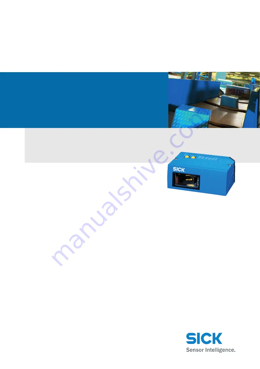
CLV65xBar Code Scanner
Page 1: ...OPERATING INS TRUCTIONS Advanced Line CLV65x Bar Code Scanner ...
Page 2: ...tion in the USA and other countries AcrobatTM ReaderTM is a trademark of Adobe Systems Incorporated Latest manual version For the latest version of this manual PDF see www sick com Software Tool Function Version Bar code scanner CLV65x SICK firmware V 3 00 Device Description CLV65x Device specific software module for SOPAS ET configuration software From v 3 00 SOPAS ET Configuration software From ...
Page 3: ... 4 6 Bar code scanner s methods of operation 28 4 7 Control elements and indicators 38 5 Installation 43 5 1 Overview of installation sequences 43 5 2 Installation preparations 43 5 3 Installation location 45 5 4 Installation of the bar code scanner 50 5 5 Installation of external components 51 5 6 Removing the bar code scanner 52 6 Electrical installation 53 6 1 Overview of installation sequence ...
Page 4: ...10 2 Data sheet for the CLV65x bar code scanner line scanner with oscillating mir ror 83 10 3 Addition to UL certification 83 10 4 Specification diagrams 84 10 5 CLV65x bar code scanner diminsional drawings 103 11 Appendix 107 11 1 Appendix overview 107 11 2 Configuring the bar code scanner with command strings 107 11 3 Calculating the code length of a bar code 108 11 4 Dimensional drawing accesso...
Page 5: ...le Power CW Codewinkel code angle DOF Depth Of Field ESD Electro Static Discharge HTML Hyper Text Markup Language I Input LED Light Emitting Diode LPS Limited Power Supply MAC Medium Access Control MTTF Mean Time To Failure MTTR Mean Time To Repair O Output PROM Programmable Read Only Memory RA Reading Angle RAM Random Acces Memory ROM Read Only Memory RTF Rich Text Format standardised document fo...
Page 6: ...plug 57 Tab 6 6 Recommended maximum cable lengths depending on the selected data transfer rate 59 Tab 6 7 Ratings for the switching inputs 62 Tab 6 8 Ratings for the switching outputs 63 Tab 6 9 Pin assignment of the 4 pole M12 plug and the 6 pole RJ45 plug 64 Tab 6 10 Pin assignment of the 12 pole M12 socket and the 15 pole D Sub HD plug 64 Tab 6 11 Pin assignment of the 12 pole M12 socket and wi...
Page 7: ... 45 Fig 5 3 Allocation of the scanning line s for the bar code and conveyor system 46 Fig 5 4 Definition of the reading distance a and the aperture angle α 46 Fig 5 5 Line scanner Reading angles that occur between the scanning line and bar code 47 Fig 5 6 Avoiding surface reflection using the line scanner as an example Angle between emitting light and bar code tilted away from the plumb line 48 Fi...
Page 8: ...ax reading distance depending on the focus position and the aperture angle with a resolution of 0 25 mm 9 8 mil 92 Fig 10 9 Depth of field ranges of the CLV650 line scanner with oscillating mirror side reading window min und max reading distance depending on the focus position and the aperture angle with a resolution of 0 35 mm 13 8 mil 93 Fig 10 10 Depth of field ranges of the CLV650 line scanner...
Page 9: ...tandard version Dimensions of the bar code scanner with oscilliating mirror CLV65x 6000 104 Fig 10 22 Ethernet version Dimensions of bar code scanners with front reading window CLV65x 0120 105 Fig 10 23 Ethernet version Dimensions of the bar code scanner with oscilliating mirror CLV65x 6120 106 Fig 11 1 Dimensions of the fixing bracket no 2020410 109 Fig 11 2 Dimensions of the quick release clamp ...
Page 10: ...Chapter Operating Instructions CLV65x Bar Code Scanner 10 SICK AG Division Auto Ident Germany All rights reserved 8011980 0000 2009 04 21 Figures and Tables ...
Page 11: ...e following tasks Tab 1 1 Target group 1 3 Depth of information This document contains all the required information for installation electrical installation and operation of the bar code scanner at the installation location The factory default set ting basic configuration of the bar code scanner is prepared for the use as a stand alone device Configuration of the bar code scanner for the applicati...
Page 12: ...important note informs you about specific features Explanation An explanation provides background knowledge of technical nature Recommendation A recommendation helps you to carry out tasks correctly TIP A tip explains setting options in the SOPAS ET configuration software PROJECT This type of script denotes a term in the user interface in the SOPAS ET configuration software A symbol indicates a bu...
Page 13: ...uired qualification for starting up the bar code scanner Tasks Qualification Installation maintenance Practical technical training Knowledge of current health and safety regulations at the work place Electricalinstallation device replacement Practical electrical training Knowledge of current electrical safety regulations Knowledge of start up and operation of the device in each operati onal area e...
Page 14: ...and electrical installation or changes to the SICK software The bar code scanner is only to be operated in ambient air temperature limit 2 3 General safety precautions and protection measures Read the general safety precautions thoroughly and observe them during all bar code scanner activities Also observe the warning notices above the operational instructions of each chapter 2 3 1 Electrical inst...
Page 15: ...equired to ensure compliance with laser class 2 Damage to the eyes through laser radiation The bar code scanner operates with a red light laser of class 2 Looking at the laser s light path for a longer period of time can damage the eye s retina The entire reading window is the LED radiation outlet opening Caution use of controls or adjustments or performance of procedures other than those specifie...
Page 16: ...b 2 2 Laser data of CLV65x Important If the bar code scanner is installed in a machine panelling in such a way that the bar code scanner s laser warning sign is hidden additional warning signs in the same language not included in delivery have to be attached to the machine next to the outlet opening of the laser radiation Standard version Ethernet version Device CLV650 CLV651 Laser out radiation m...
Page 17: ...ng operation the LEDs have got additional display functions The Laser LED will differ from its original function It is possible that the Laser LED is flashing when Auto setup is selected although the laser diode is still switched off or the laser diode is swit ched on for example in diagnostic mode Read Diagn and the Laser LED however is not flashing 2 4 Quick stop and quick restart The bar code s...
Page 18: ...es the following energy Line scanner Typically 8 5 W with 18 30 V DC Line scanner with oscillating mirror Typically 9 5 W with 18 30 V DC All values with unwired switching outputs 2 5 2 Dispose of the device after decommissioning SICK AG will not currently accept the return of any devices which can no longer be operated or repaired Inoperable or irreparable devices must be disposed of in an enviro...
Page 19: ...interfaces see ordering information for Bar Code Scanner CLV600 product infor mation 3 wire RS 232 data cable null modem cable no 2014054 or To connect an Ethernet version of the bar code scanner to the PC s Ethernet interface relevant cable see ordering information for Bar Code Scanner CLV600 product infor mation Perform an electrical connection to the bar code scanner 1 Connect the bar code scan...
Page 20: ...tablish communication with the bar code scanner page 68 and perform a scan TIP To establish a connection quickly and easily via Ethernet the SOPAS ET configuration soft ware has a CONNECTION WIZARD in the TOOLS menu 3 3 Performing the reading Fig 3 1 Quickstart register tab of SOPAS ET configuration software Note For the SOPAS ET configuration software the QUICKSTART register tab contains the most...
Page 21: ...indow and trigger the reading by clicking START If necessary observe the bar code scanner s depth of fields ranges depending on resolution see chapter 10 4 Specifica tion diagrams page 84 During reading operation and with default settings the line scanner with oscillating mir ror deflects the scanning line by the central position with a frequency of 1 Hz and at a max angle of 20 The reading result...
Page 22: ...Chapter 3 Operating Instructions CLV65x Bar Code Scanner 22 SICK AG Division Auto Ident Germany All rights reserved 8011980 0000 2009 04 21 Quick Start ...
Page 23: ...s with auto focus can be switched off and an electronic unit with an integrated decoder The laser scanner and electronic unit are located in a housing The light exits and enters via a reading window in the industrial type housing The bar code scanner depending on the version is electrically connected by a cable with a connector or a revolving connector unit with two con nections For an adaption to...
Page 24: ...g Instructions CLV65x Bar Code Scanner 24 SICK AG Division Auto Ident Germany All rights reserved 8011980 0000 2009 04 21 Product description Fig 4 2 Device view of the CLV65x bar code scanner shown here Ethernet Version ...
Page 25: ...at Reader Freely available PC software for reading PDF files Important The current versions of publications and programs on the CD ROM can also be downloaded at www sick com Piece s Components Comment 1 Bar code scanner CLV650 CLV651 depending on version 1 Set of laser warning signs for class 2 in German American English and French American English Self adhesive to affix the warning sign to the ba...
Page 26: ...ystem requirements derive from the bar code scanner s technical data see chapter 10 Technical data page 81 The requirements and conditions for Installation Electrical installation and Startup and configuration are summarised in the respective chapters Order no Type Scanning method Reading window Connection design 1041290 CLV650 0000 Line scanner On front Cable with connector 1042121 CLV650 0120 Li...
Page 27: ... data interface Future proof SOPAS ET configuration software Low current consumption Extended power supply range Convenient operation configuration Configuration online offline using the SOPAS ET configuration software incl help system Auto Setup of optical reading properties Profile programming with bar codes created and printed via SOPAS ET 2 buttons on the device for calling up preset functions...
Page 28: ...bar code is recorded processed and decoded To control this process external sensors deliver information via the reading pulse the object distance and the conveyor speed increment The reading results are output to the bar code scanner s data interfaces and forwarded to a host PC Electrical interfaces Host interface RS 232 RS 422 485 data format and protocol can be configured and Ethernet or CAN Aux...
Page 29: ...are described in chapter 6 Electrical installation page 53 4 6 1 Reading configuration The bar code scanner detects bar codes with an adjustable scan frequency The bar code scanner can detect codes on resting and moving objects For more rapid evaluation the reading range of the scanning line reading angle RA value can be restricted Note The SOPAS ET configuration software can among other things be...
Page 30: ...e reading pulse sensor a time window opens in the bar code scanner reading gate for the reading process Alternatively a command activates the reading process via a data interface or the CAN SEN SOR network In Automatic Cycle mode the actual bar code scanner generates the reading gate internally with an adjustable mark space ratio The reading pulse can be ended in a number of ways With external tri...
Page 31: ...rotrude constantly into the reading plane Only one object with barcode s is in side the reading field during one reading pulse The distance profile of the background can also be displayed in the SOPAS ET configuration software The autofocus range is defined by the aperture angle the autofocus space and in the case of line scanners with oscillating mirror also by the angle of deflection The park se...
Page 32: ...c tion of object height Trigger sources for the switch over are Signal at the switching input Sensor 2 for max 2 pole switching Command from the host interface or the integrated timer e g search run for the max 8 pole switch over Reversal points of oscillation mirror for the bilateral deflection on the line scanner with oscillating mirror see chapter 4 6 5 Oscillating mirror control page 33 The di...
Page 33: ...e reading pulse n fold oscillation around an adjustable start position within the reading pulse one shot one time deflection forward and return per reading pulse from an adjustable start position In every oscillation mode the amplitude can be adjusted separately for each of the two de flection directions The deflection speed ratio of one deflection direction to the other can be adjusted within the...
Page 34: ...ternal incremental encoder 4 6 7 Code configuration The bar code scanner can decode the following code types Codabar Code 39 UPC EAN 2 5 Interleaved Code 93 Code 128 family Pharmacode Note The increment source and the resolution speed can be configured using the SOPAS ET con figuration software PROJECT TREE CLV65X PARAMETER INCREMENT CONFIGURATION INCREMENT register tab Note The code types can be ...
Page 35: ...er at the end of the rea ding pulse the rear edge of the object has left the end of the reading field or during the reading pulse if certain configurable conditions have been fulfilled Fig 4 7 Reading operation mode for the CLV65x bar code scanner in stand alone operation 4 6 9 Data processing Note The reading operation mode can be configured using the SOPAS ET configuration software PROJECT TREE ...
Page 36: ...sion Tab 4 4 Data interface function Note The output formats can be configured using the SOPAS ET configuration software PROJECT TREE CLV65X PARAMETER DATA PROCESSING OUTPUT FORMAT Note The network parameters can be configured using the SOPAS ET configuration software PROJECT TREE CLV65X PARAMETER NETWORK INTERFACE IOS NETWORK OPTIONS register tabs Data interface Function Host interface RS 232 or ...
Page 37: ...Digital outputs With certain events in the reading process e g for unsuccessful decoding No Read two independent switch signals can be generated at both digital outputs and can be used e g to display the event status Important The switching outputs Result 1 and Result 2 are only available in the standard version of the bar code scanner For the Ethernet version of the bar code scanner the two outpu...
Page 38: ...LEDs on the bar code scanner s housing The bar code scanner s housing has six LEDs displaying the operating status the laser dio de s activity the status of the reading result and the transfer to the RS 232 RS 422 485 CAN and Ethernet interfaces In reading operation the LEDs indicate the following Tab 4 5 LED indications Important The Result LED is not coupled with one of the Result 1 or Result 2 ...
Page 39: ... via the corresponding LED below the buttons When using both of the buttons the LEDs have different meanings than in normal reading operation Tab 4 6 Meaning of the LEDs during activation of buttons Important When using the buttons the Laser LED s function differs from its original function in rea ding operation the display of the switched on laser diode LED Colour Function Read Diagn green Flashe...
Page 40: ...le functions successively without starting them and starts over The beeper confirms each step with a sound 3 Press the upper button once to start the selected function The LED flashes faster and the beeper confirms the start with two sounds 4 Press the upper button again to stop the function The LED flashes more slowly again and the beeper confirms the end with two sounds The bar code scanner stop...
Page 41: ...operating mode and restarts the reading operation The bee per confirms the change with a descending melody If no function is started in button operating mode or if no button operation can be per formed after using a function the bar code scanner returns into reading operation au tomatically after 30 seconds The beeper confirms the change with a descending melody The bar code scanner terminates an ...
Page 42: ...ved and inserted into the new device after the respective bar code scanner has been switched off and de energized When inserting the memory card make sure that the contacts point backwards and upwards towards the inscription mircoSD on the box slot The memory card is located behind a black rubber cover attached to the bar code scanner Fig 4 8 Micro SD memory card for storing the parameter set Impo...
Page 43: ...lse triggering Important Do not open the bar code scanner s housing If the device is opened the SICK AG warranty shall not apply 5 2 Installation preparations Observe the following general requirements for installation Typical space requirement application specific Unobstructed view of the objects for the bar code scanner Stable installation bracket with sufficient load capacity and measurements s...
Page 44: ...nted using the following SICK holders Bracket no 2020410 Quick release clamp no 2025526 Bracket no 2042800 Round rod holder no 2042801 The construction of the angle with adapter plate no 2042800 supports e g varied moun ting options and the alignment of the bar code scanner in two axis Fig 5 1 Example Fixing the bar code scanner with the bracket no 2042800 The dimensioning of the SICK holders is s...
Page 45: ...fore operating the bar code scan ner Fig 5 2 Exchanging the laser warning sign 5 3 Installation location The following aspects are relevant for the selection of the installation location Allocation of the scanning line for the bar code Reading distance to the bar code and aperture angle α Angle alignment of the bar code scanner Avoiding surface reflections Counting direction of the reading angle p...
Page 46: ... system 5 3 2 Reading distance to the bar code and aperture angle α The maximum distance between the bar code scanner s reading window and the bar code must not exceed the device specific thresholds The usable length of the scanning line that is used for the evaluation reading area height depends on the reading distance because of the V shaped deflection of the beam Fig 5 4 Definition of the readi...
Page 47: ...code positions that can occur between the scanning line and bar code in all three levels of the room Fig 5 5 Line scanner Reading angles that occur between the scanning line and bar code Tab 5 1 Permitted reading angles between the scanning line and bar code α Azimut angle tilt β Inclination angle pitch γ Step angle skew a Reading distance b Reading range Angle Threshold Azimut α tilt max 30 resol...
Page 48: ...ection using the line scanner as an example Angle between emitting light and bar code tilted away from the plumb line 5 3 5 Counting direction of the reading angle and code angle The bar code scanner can scan and decode several bar codes with every reading process The location related reading diagnosis data is determined The reading angle from the reading window to the red scanning line of the def...
Page 49: ...to be separated and the bar code data to be assigned to their position on the object Fig 5 7 Counting direction of the reading angle RA within the scanning line and of the code angle CW with oscillating mirror Line scanner front reading window Line scanner with oscillating mirror side reading window Reading angle α aperture angle in the scanning direction 1 2 RA 50 100 RA Deflection angle of the s...
Page 50: ...surface When using the bar code scanner with side reading window respectively the line scanner with oscillating mirror ensure that the wide side panel with the LEDs is fa cing the viewer and is approximately parallel with the bar code surface During the reading process consider the reading angle see chapter 5 3 3 Angle alignment of the bar code scanner page 47 If the bar code s position within the...
Page 51: ...triggered by an external reading pulse sensor photoelectric reflex switch the sensor has to be installed close to the bar code scanner Fig 5 8 Line scanner Installation example for positioning the external reading pulse sensor The sensor s installation location depends on the distance a of the bar code to the front edge of the object Depending on the application the sensor should be attached in su...
Page 52: ...nt impulses have to come from the conveyor system area where the bar code scanner is reading 1 Install suitable increment encoders near to the bar code scanner best against the di rection of the conveyor system in front of the bar code scanner 2 Ensure that the incremental encoder has direct and fixed contact with the drive system and that the friction wheel rotates without slipping 5 6 Removing t...
Page 53: ...ply voltage 18 30 V DC functional extra low voltage in accordance with IEC 60364 4 41 VDE 0100 Part 410 and min 10 W output power Using connection module CDB620 CDM420 supply voltage provided by terminals of the connection module or Free wiring by customer without connection module CDB620 CDM420 connec tion of supply voltage e g by cable no 6034418 15 pole D Sub HD socket to open end With external...
Page 54: ...ny All rights reserved 8011980 0000 2009 04 21 Electrical installation 6 3 Electrical connections and cables Fig 6 1 Standard version Electrical connections at the bar code scanner with connection cable Fig 6 2 Ethernet version Electrical connections at the bar code scanner with connector unit ...
Page 55: ...tor standard version Tab 6 2 Electrical connections to the bar code scanner with connector unit Ethernet version Important Additional digital inputs and outputs are available at connection module CDB620 CDM420 available from week 07 2008 in combination with the parameter memory module CMC600 Device version Connection design Interfaces For connection to CLV65x 0000 CLV65x 1000 CLV65x 2000 CLV65x 30...
Page 56: ...ux Aux interface receiver 3 TxD Aux Aux interface sender 4 Sensor 2 Digital switching input adjustable func tion e g external reading pulse 5 GND Ground 6 RD RS 422 485 Host interface receiver 7 RD RS 422 485 RxD RS 232 Host interface receiver 8 TD RS 422 485 Host interface sender 9 TD RS 422 485 TxD RS 232 Host interface sender 10 CAN H CAN bus IN OUT 11 CAN L CAN bus IN OUT 12 Result 1 Digital s...
Page 57: ...for the Ethernet version via the CDB620 CDM420 connection module in combination with the parameter memory module CMC600 Pin Signal Function 1 GND Ground 2 18 30 V DC Supply voltage 3 CAN L CAN bus IN OUT 4 CAN H CAN bus IN OUT 5 TD RS 422 485 Host interface sender 6 TD RS 422 485 TxD RS 232 Host interface sender 7 TxD Aux Aux interface sender 8 RxD Aux Aux interface receiver 9 SensGND Switching in...
Page 58: ...quires a supply voltage of 18 30 V functional extra low voltage in accordance with IEC 60364 4 41 VDE 0100 Part 410 The functional extra low voltage can be created using a safety transformer in accordance with IEC 742 VDE 0551 The ma ximum current consumption is 8 5 9 5 W The bar code scanner is supplied with 18 30 V DC via connection module CDB620 or CDM420 If the power supply module CMP400 CMP49...
Page 59: ... plug to the connection module s 15 pole socket and screw it tight or Ethernet version Connect the bar code scanner s 12 pole plug via a corresponding ca ble e g 2042916 to the connection module s 15 pole socket and screw it tight 6 4 2 Wiring serial data interfaces The maximum data transfer rate depends on the cable length and the interface type Tab 6 6 Recommended maximum cable lengths depending...
Page 60: ...elded cables Adhere to the maximum cable lengths 2 To prevent interference do not lay cables parallel to power supply cables and motor lines over a longer distance e g in cable channels CLV Host Host CLV RS 232 RS 422 Damage to the interface module Incorrect wiring of the serial data interfaces can damage electronic components in the bar code scanner Observe information about wiring the serial dat...
Page 61: ...nterface communication can also be executed in parallel via the Ethernet in terface Fig 6 5 Function of the Ethernet interface Important The Ethernet interface has an auto MDIX function This automatically sets the speed and any cross connection that is required Important To wire and configure the bar code scanner s CAN interface for use in the CAN SENSOR net work see the operating instructions Usi...
Page 62: ... functions among others Trigger source for Incremental encoder input Reading pulse generator for reading pulse end Fig 6 7 Wiring the Sensor 2 switching input on the 15 pole D Sub HD plug Important The ratings for Sensor 1 and Sensor 2 are identical Tab 6 7 Ratings for the switching inputs Connect switching inputs depending on application Switching behaviour Power fed to the input opens the intern...
Page 63: ...tching behaviour Threshold is a max capacitance of 100 nF Exeeding this value can lead to unwanted pulsing behaviour of the output 1 Connect switching outputs depending on application 2 Wire the switching outputs with a load resistance to test the switching functions using a high resistance digital voltmeter Indication of incorrect voltages switching statuses is avoided this way Important To wire ...
Page 64: ...e 12 pole M12 socket and the 15 pole D Sub HD plug Pin 4 pole Signal Function Pin 6 pole 1 TD Transmitter 1 3 TD Transmitter 2 2 RD Receiver 3 4 5 4 RD Receiver 6 Shield Pin 12 pole Signal Function Pin 15 pole 2 18 30 V DC Supply voltage 1 8 RxD Aux Aux interface receiver 2 7 TxD Aux Aux interface sender 3 4 1 GND Ground 5 11 RD RS 422 485 Host interface receiver 6 12 RD RS 422 485 RxD RS 232 Host...
Page 65: ...nction Wire colour 1 GND Ground brown 2 18 30 V DC Supply voltage blue 3 CAN L CAN bus IN OUT white 4 CAN H CAN bus IN OUT green 5 TD RS 422 485 Host interface sender pink 6 TD RS 422 485 TxD RS 232 Host interface sender Yellow 7 TxD Aux Aux interface sender black 8 RxD Aux Aux interface receiver grey 9 SensGND Common ground for the switching inputs Red 10 Sensor 1 Digital switching input for exte...
Page 66: ...Sensor 2 Digital switching input adjustable function e g external reading pulse red black 5 GND Ground black 6 RD RS 422 485 Host interface receiver light blue 7 RD RS 422 485 RxD RS 232 Host interface receiver blue 8 TD RS 422 485 Host interface sender light grey turquoise 9 TD RS 422 485 TxD RS 232 Host interface sender green 10 CAN H CAN bus IN OUT grey 11 CAN L CAN bus IN OUT pink 12 Result 1 ...
Page 67: ... bar code scanner if necessary Check correct functioning of the bar code scanner in reading operation 7 2 SOPAS ET configuration software The SOPAS ET configuration software optimises the bar code scanner to the reading condi tions on site The configuration data can be saved and archived as a parameter set project file on the PC 7 2 1 Functions of the SOPAS ET configuration software for the bar co...
Page 68: ...perating instructions to conclude installation 7 2 4 Default setting for SOPAS ET configuration software Tab 7 1 Default setting for the SOPAS ET configuration software excerpt 7 3 Establish communication with the bar code scanner Prerequisite The TCP IP protocol at the PC has to be active to enable communication via TCP IP 7 3 1 Connecting data interfaces Connect the PC and bar code scanner via o...
Page 69: ...are has a CONNECTION WIZARD in the TOOLS menu Manual configuration 1 In the dialog window SCAN ASSITANT under INTERNET PROTOCOL INTERNET PROTOCOL IP check the check box for ENABLE IP COMMUNICATION 2 Click on the ADD button 3 Enter the IP address of the bar code scanner and confirm it by pressing OK in the dialog window The dialog window closes A new entry appears in the IP ADDRESS CONFIGURATION li...
Page 70: ... or to the CMC600 repectively with every permanent storage of the parameter set to the bar code scanner After the bar code scanner is restarted the data from the memory card repectively from the CMC600 is automatically transferred to the bar code scanner As such a bar code scanner can be exchanged for example without losing configuration data see chapter 8 5 Replac ing a bar code scanner page 78 I...
Page 71: ... If the parameter set is password protected enter the password client in PASSWORD Activate deactivate password protection on the PARAMETER register tab 3 Click on OK to confirm the dialog window The previously greyed out parameters on the register tabs are now accessible 7 4 3 Permanently load changed parameter sets into the device Changed parameter values are immediately transferred to the bar co...
Page 72: ... AS PDF FILE command in the menu bar under PROJECT 7 5 Default setting The values of the default setting are permanently saved in the bar code scanner ROM and in the database of the SOPAS ET configuration software in the device specific jar file see chapter 7 4 First startup page 70 A PC is not required to start up the bar code scanner with the default setting 7 5 1 Resetting the default setting i...
Page 73: ...n module CDB620 CDM420 with parameter memory module CMC600 the default setting will be permanently transferred to parameter memory CMC600 or me mory card respectively Important Once the default setting has been restored password protection is deactivated 7 6 Adjusting the bar code scanner 7 6 1 Adjusting the bar code scanner To completely adjust the bar code scanner the electrical installation mus...
Page 74: ...Chapter 7 Operating Instructions CLV65x Bar Code Scanner 74 SICK AG Division Auto Ident Germany All rights reserved 8011980 0000 2009 04 21 Startup and configuration ...
Page 75: ...n humidity finger prints etc The type place displays the window material used for the reading window CLV65x xxxy y 0 Glass y 1 Plastic Damage to the eyes through laser radiation The bar code scanner operates with an red light laser of class 2 Looking at the laser s light path for a longer period of time can damage the eye s retina The entire reading window is the LED radiation outlet opening Cauti...
Page 76: ...ning fluid Only clean the plastic reading window with a clean damp lint free cloth and a mild anti static window cleaning fluid Damage to the reading window Reduced reading capacity due to scratches or smears on the reading window The reading window for versions CLV65x xxx0 is made of glass Do not use aggressive cleaning agents Do not use cleaning agents which cause increased abrasion e g powder A...
Page 77: ... housing of dust If necessary also clean the LEDs on the housing 8 3 Cleaning further optical effective surfaces Depending on the reading system equipment additional external sensors with optical effec tive surfaces can be installed e g photoelectric reflex switch for external reading pulsing Soiling of these sensors can cause incorrect switching behaviour In order to prevent incorrect switching b...
Page 78: ...is carefully open the black rubber cover and slightly press on the memory card in order to unlock it 5 Insert the memory card accordingly into the empty space of the new turned off bar code scanner the right way round contacts to the back and top until it is locked 6 Close the rubber cover 8 5 2 Replacing the bar code scanner 1 Align and install the new or repaired bar code scanner see chapter 5 I...
Page 79: ...rror Functions have not been adjusted to the local conditions e g parameters for the data interface set incorrectly Device related limits have not been considered e g reading distance aperture angle Selected trigger source for reading pulse incorrect 9 1 4 Malfunctions during operation Start Stop operation External reading pulse is missing more than one object is in the reading area Device error h...
Page 80: ... the SOPAS ET configuration software has to be online and connected to the bar code scanner 1 Connect the SOPAS ET configuration software with the device 2 Open the project tree CLV65X SERVICE SYSTEM STATUS SYSTEM INFORMATION Register tab 9 4 SICK Support If an error cannot be eliminated it is possible that the bar code scanner is defective The bar code scanner cannot be repaired by the user meani...
Page 81: ... CAN Print ratio 2 1 3 1 Number of multireads 1 99 Memory card for parameters cloning Micro SD card flash card 512 MB optional Optical indicators 6 LEDs Ready Result Laser Data CAN LNK TX and bargraph display Acoustic display Beeper can be switched off with function for result status display Control elements 2 buttons selecting and starting stopping functions Reading pulsing Pulse sources for star...
Page 82: ...6 04 Enclosure rating III according to EN 61140 2002 03 Enclosure rating IP 65 according to EN 60529 1991 10 A1 2002 02 EMV tested Emission according to EN 61000 6 3 2007 01 immunity according to EN 61000 6 2 2005 08 Vibration shock test According to EN 60068 2 6 1995 to EN 60068 2 27 1993 Weight Standard version 320 g 11 3 oz with connection cable front reading window 340 g 12 0 oz side reading w...
Page 83: ...d or Continuous free oscillation Controlled operation start stop condition can be adjusted Triggered oscillation start position and number of oscillations can be adjusted One shot One time oscillation in forward and return motion start position can be adjusted In every oscillation mode the amplitude can be adjusted separately for each of the two deflection directions The deflection speed ratio of ...
Page 84: ...erving the reading area diagram see figure of the CLV65x of a module width at a focus position from the top the selections 1 2 and 3 can be transferred to the depth of focus diagram for this module width as follows Therefore the depth of focus diagram consists of a slice shaped sequence of many reading area diagrams along the focus position Test code Code 39 ITF Print ratio 2 1 Print contrast 90 T...
Page 85: ...er 10 CLV65x Bar Code Scanner Technical data 8011980 0000 2009 04 21 SICK AG Division Auto Ident Germany All rights reserved 85 Fig 10 1 Meaning of selection 1 2 and 3 in the reading area diagram related to depth of focus diagram ...
Page 86: ... rights reserved 8011980 0000 2009 04 21 Technical data 10 4 1 Depth of field ranges of the CLV650 line scanner with front reading window Fig 10 2 Depth of field ranges of the CLV650 line scanner with front reading window Resolutions 0 25 mm 9 8 mil 0 35 mm 13 8 mil 0 5 mm 19 7 mil and 1 0 mm 39 4 mil ...
Page 87: ...0 0000 2009 04 21 SICK AG Division Auto Ident Germany All rights reserved 87 Fig 10 3 Depth of field ranges of the CLV650 line scanner with front reading window min und max reading distance depending on the focus position and the aperture angle with a resolution of 0 25 mm 9 8 mil ...
Page 88: ...to Ident Germany All rights reserved 8011980 0000 2009 04 21 Technical data Fig 10 4 Depth of field ranges of the CLV650 line scanner with front reading window min und max reading distance depending on the focus position and the aperture angle with a resolution of 0 35 mm 13 8 mil ...
Page 89: ...0 0000 2009 04 21 SICK AG Division Auto Ident Germany All rights reserved 89 Fig 10 5 Depth of field ranges of the CLV650 line scanner with front reading window min und max reading distance depending on the focus position and the aperture angle with a resolution of 0 5 mm 19 7 mil ...
Page 90: ...uto Ident Germany All rights reserved 8011980 0000 2009 04 21 Technical data Fig 10 6 Depth of field ranges of the CLV650 line scanner with front reading window min und max reading distance depending on the focus position and the aperture angle with a resolution of 1 0 mm 39 4 mil ...
Page 91: ... Ident Germany All rights reserved 91 10 4 2 Depth of field ranges of the CLV650 line scanner with oscillating mirror side reading window Fig 10 7 Depth of field ranges of the CLV650 line scanner with oscillating mirror side reading window Resolutions 0 25 mm 9 8 mil 0 35 mm 13 8 mil 0 5 mm 19 7 mil and 1 0 mm 39 4 mil ...
Page 92: ... Germany All rights reserved 8011980 0000 2009 04 21 Technical data Fig 10 8 Depth of field ranges of the CLV650 line scanner with oscillating mirror side reading window min und max reading distance depending on the focus position and the aperture angle with a resolution of 0 25 mm 9 8 mil ...
Page 93: ...9 04 21 SICK AG Division Auto Ident Germany All rights reserved 93 Fig 10 9 Depth of field ranges of the CLV650 line scanner with oscillating mirror side reading window min und max reading distance depending on the focus position and the aperture angle with a resolution of 0 35 mm 13 8 mil ...
Page 94: ...Germany All rights reserved 8011980 0000 2009 04 21 Technical data Fig 10 10 Depth of field ranges of the CLV650 line scanner with oscillating mirror side reading window min und max reading distance depending on the focus position and the aperture angle with a resolution of 0 5 mm 19 7 mil ...
Page 95: ...9 04 21 SICK AG Division Auto Ident Germany All rights reserved 95 Fig 10 11 Depth of field ranges of the CLV650 line scanner with oscillating mirror side reading window min und max reading distance depending on the focus position and the aperture angle with a resolution of 1 0 mm 39 4 mil ...
Page 96: ...reserved 8011980 0000 2009 04 21 Technical data 10 4 3 Depth of field ranges of the CLV651 line scanner with front reading window different aperture and inclination angle Fig 10 12 Depth of field ranges of the CLV651 line scanner with front reading window Resolution 0 5 mm 19 7 mil and inclination angle 0 45 ...
Page 97: ...nner Technical data 8011980 0000 2009 04 21 SICK AG Division Auto Ident Germany All rights reserved 97 Fig 10 13 Depth of field ranges of the CLV651 line scanner with front reading window Resolution 0 5 mm 19 7 mil inclination angle 0 aperture angle 25 55 ...
Page 98: ...ner 98 SICK AG Division Auto Ident Germany All rights reserved 8011980 0000 2009 04 21 Technical data Fig 10 14 Depth of field ranges of the CLV651 line scanner with front reading window Resolution 0 5 mm 19 7 mil inclination angle 45 aperture angle 25 55 ...
Page 99: ...to Ident Germany All rights reserved 99 10 4 4 Depth of field ranges of the CLV651 line scanner with oscillating mirror different aperture and inclination angle Fig 10 15 Depth of field ranges of the CLV651 line scanner with oscillating mirror side reading window Resolution 0 5 mm 19 7 mil and inclination angle 0 45 ...
Page 100: ...ICK AG Division Auto Ident Germany All rights reserved 8011980 0000 2009 04 21 Technical data Fig 10 16 Depth of field ranges of the CLV651 line scanner with oscillating mirror side reading window Resolution 0 5 mm 19 7 mil inclination angle 0 aperture angle 25 55 ...
Page 101: ...ical data 8011980 0000 2009 04 21 SICK AG Division Auto Ident Germany All rights reserved 101 Fig 10 17 Depth of field ranges of the CLV651 line scanner with oscillating mirror side reading window Resolution 0 5 mm 19 7 mil inclination angle 45 aperture angle 25 55 ...
Page 102: ...80 0000 2009 04 21 Technical data 10 4 5 Deflection range of line scanner with oscillating mirror Fig 10 18 CLV650 Deflection range as a function of the reading distance deflection angle and resolution Fig 10 19 CLV651 Deflection range as a function of the reading distance deflection angle and resolution of 0 5 mm 19 7 mil ...
Page 103: ...0 0000 2009 04 21 SICK AG Division Auto Ident Germany All rights reserved 103 10 5 CLV65x bar code scanner diminsional drawings 10 5 1 CLV65x 0000 bar code scanner diminsional drawings Fig 10 20 Standard version Dimensions of bar code scanners with front reading window CLV65x 0000 ...
Page 104: ...er 104 SICK AG Division Auto Ident Germany All rights reserved 8011980 0000 2009 04 21 Technical data 10 5 2 CLV65x 6000 bar code scanner diminsional drawings Fig 10 21 Standard version Dimensions of the bar code scanner with oscilliating mirror CLV65x 6000 ...
Page 105: ...ner Technical data 8011980 0000 2009 04 21 SICK AG Division Auto Ident Germany All rights reserved 105 10 5 3 CLV65x 0120 bar code scanner diminsional drawings Fig 10 22 Ethernet version Dimensions of bar code scanners with front reading window CLV65x 0120 ...
Page 106: ...er 106 SICK AG Division Auto Ident Germany All rights reserved 8011980 0000 2009 04 21 Technical data 10 5 4 CLV65x 6120 bar code scanner diminsional drawings Fig 10 23 Ethernet version Dimensions of the bar code scanner with oscilliating mirror CLV65x 6120 ...
Page 107: ...ands are at first only active in the current parameter set in the working memory RAM of the bar code scanner To save in the permanent memory the altered parameter set must be copied into the PROM using a special command this ensures that the alterations are not lost when the power sup ply is switched off Command strings for triggering the reading pulse START STX sMN mTCgateon ETX STOP STX sMN mTCg...
Page 108: ...on software Code 39 Number of bars Number 10 ICode 5 Calculated code length 2 5 Interleaved Number of wide elements bars and spaces Number 1 ICode 2 Calculated code length EAN n a 13 characters normal version Activate 13 digit 8 characters short version Activate 8 digit UPC n a 12 characters UPC A normal ver sion Activate version A 6 characters UPC E short version Activate version E Codabar Number...
Page 109: ...to Ident Germany All rights reserved 109 11 4 Dimensional drawing accessories 11 4 1 Dimensional drawing fixing bracket no 2020410 Fig 11 1 Dimensions of the fixing bracket no 2020410 Included to fix the bar code scanner to the bracket 2 x cylinder head screws M5 x 8 mm 0 32 in with hexagon socket self locking ...
Page 110: ... All rights reserved 8011980 0000 2009 04 21 Appendix 11 4 2 Dimensional drawing of quick release clamp no 2025526 Fig 11 2 Dimensions of the quick release clamp no 2025526 Included to fix the bar code scanner to the clamp 2 x cylinder head screws M5 x 8 mm 0 32 in with hexagon socket self locking ...
Page 111: ...ision Auto Ident Germany All rights reserved 111 11 4 3 Dimensional drawing fixing bracket no 2042800 Fig 11 3 Dimensions of the fixing bracket no 2042800 Included to fix the bar code scanner to the bracket 3 x cylinder head screws M5 x 8 mm 0 32 in with hexagon socket self locking 3 x spring washer A5 ...
Page 112: ...hts reserved 8011980 0000 2009 04 21 Appendix 11 4 4 Dimensional drawing of round rod holder no 2042801 Fig 11 4 Dimensions of the round rod holder no 2042801 Included to fix the bar code scanner to the holder 3 x cylinder head screws M5 x 8 mm 0 32 in with hexagon socket self locking 3 x spring washer A5 ...
Page 113: ... the host PLC sensor using con nection module CDM420 8012120 Operating instructions Parameter memory module CMC600 German English Description of operating the module in con nection module CDB620 or CDM420 8010372 Operating instructions Display module CMD400 German English Description of operating the module in con nection module CDM420 8010365 Operating instructions Power supply module CMP400 Germ...
Page 114: ... the oscillating mirror across the scanning direction to both sides of the central position CW 50 corresponds to a light exit under 105 default setting Also called oscillation amplitude Deflection angle Angle which the scanning line covers at both sides each of the central position CW 50 cor responds to 0 when deflected by the oscillating mirror Also called oscillation angle Autofocus function Abi...
Page 115: ...d spaces can be more easily analysed by the reading device User interface Windows oriented input interfaces in the SOPAS ET configuration software for operation and configuration of the bar code scanner CAN interface Physical data interface Controls construction of a rapid SICK specific CAN SENSOR network with various functions e g multiplexer master slave Access to the CLV65x bar code scanner for...
Page 116: ...er level in SOPAS ET Result status output Adjustable function of the two independent switching outputs Result 1 and Result 2 of the standard version Indicates either the status of the reading result e g good read or the fulfillment of a definable event dependent evaluation condition for the read operation such as Match1 The outputs can also be switched off individually or together The Ether net ve...
Page 117: ...e scanner to shift the focus of the laser beam within a wide ran ge on the reading level Focus position switching is event driven e g through distance detection Function interfaces Digital switching inputs and outputs of the bar code scanner Default setting The factory default setting of all of the bar code scanner s parameter values is saved in its permanent memory and can be reloaded at any time...
Page 118: ...d string form a clearly structured command language for changing the parameter value sets in the bar code scanner online Directly accesses the command inter preter of the bar code scanner Use of the host requires a corresponding programming task The SOPAS ET configuration software is based on the command strings Configuration file Project file for the SOPAS ET configuration software in which eithe...
Page 119: ...um and maximum RA values Line scanner Scanner that uses a polygon mirror wheel with paraxial mirrors to deflect a focused laser beam extremely fast As a result it creates a light spot in the reading plane that moves along a straight line which appears to the naked eye as a stationary scan line Line scanner with oscillating mirror Line scanner that also deflects the laser beam about a central posit...
Page 120: ...ng reading events diagnosis as well as for preparatory offline configuration of stand alone devices or the grouping of the same different SOPAS ET compatible SICK devices in a project The pa rameters are exchanged device specific with the bar code scanner the devices via upload and download SOPAS ET help Online help which supports use of the SOPAS ET configuration software The parameter functions ...
Page 121: ...th oscillating mirror is a result of the limits set by the active scan line range and the oscillation amplitude CW value Hence a sharp window of the same size can be generated in the reading field for every distance configuration for any read distance Teach in Method of programming the information required to adjust the CLV65x to the reading appli cation in Parameterization mode Example teaching i...
Page 122: ...C Declaration of Conformity The figure shows a scaled down version of the EC Declaration of Conformity page 1 for the CLV65x bar code scanner The complete EC Declaration of Conformity and the list of device versions and the stan dards met can be requested from SICK AG Fig 11 5 EC Declaration of Conformity for the bar code scanner page 1 scaled down version ...
Page 123: ...y All rights reserved 123 11 8 Code samples of bar codes selection Fig 11 6 Code samples of bar codes of various module widths print ratio 2 1 2 5 Interleaved EAN 13 digit Code 39 Module width 0 30 mm 11 8 mil Module width 0 35 mm 13 8 mil Module width 0 50 mm 19 7 mil 4 0 9 6 0 7 2 6 1 6 5 5 9 9 8 7 6 5 4 3 2 1 0 C L V 6 3 X ...
Page 124: ...8011980 0000 2009 04 21 DWF PM6 5 FM7 0 PDF Printed in Germany Subject to change without notice The specified product features and technical data do not represent any guarantee 05 Pre int62 ...