B E T R I E B S A N L E I T U N G
O P E R A T I N G I N S T R U C T I O N S
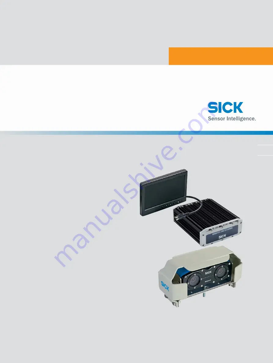
3vistor-P CV
Betriebsanleitung
Operating Instructions
3D-Fahrassistenzsystem zur Kollisionsvermeidung
3D driver assistance system for collision awareness
d e
e n
Page 1: ...A N L E I T U N G O P E R AT I N G I N S T R U C T I O N S 3vistor P CV Betriebsanleitung Operating Instructions 3D Fahrassistenzsystem zur Kollisionsvermeidung 3D driver assistance system for collision awareness de en ...
Page 2: ...gründeten Rechte bleiben bei der Firma SICK AG Die Vervielfältigung des Werks oder von Teilen dieses Werks ist nur in den Grenzen der gesetzlichen Bestimmungen des Urheberrechtsgesetzes zuläs sig Jede Änderung Kürzung oder Übersetzung des Werks ohne ausdrückliche schriftli che Zustimmung der Firma SICK AG ist untersagt Die in diesem Dokument genannten Marken sind Eigentum ihrer jeweiligen Inhaber ...
Page 3: ...are Fehlanwendung 9 2 4 Qualifikation des Bedieners 10 3 Produktbeschreibung 11 3 1 Produkteigenschaften 11 3 2 Aufbau 11 3 3 Anschlüsse 12 3 3 1 Evaluation Unit EU 12 3 3 2 Stromversorgung 12 3 3 3 Anschlussübersicht 13 3 4 Anzeigeelemente 14 3 5 Funktionsweise 14 3 5 1 Stereoskopie 14 3 5 2 Funktionsprinzip 14 3 5 3 Detektionsbereich und Alarmzone 15 3 5 4 Alarmausgabe 16 4 Transport und Lagerun...
Page 4: ...s verbinden 23 7 3 System booten 24 8 Konfiguration und Bedienung 25 8 1 3vistor P konfigurieren 25 8 1 1 Wichtige Hinweise 25 8 1 2 Symbole der HMI Steuerung 25 8 1 3 Konfiguration vornehmen 26 8 1 4 Konfiguration prüfen 30 8 2 Einrichtbetrieb 31 8 3 3vistor P bedienen 32 9 Instandhaltung und Pflege 33 9 1 Regelmäßige Prüfung 33 9 2 Instandhaltung 33 9 3 Pflege 33 10 Außerbetriebnahme 34 10 1 Sic...
Page 5: ...kteure Monteure Elektrofachleute Bediener und Instandhaltungspersonal Die Struktur dieser Betriebsanleitung orientiert sich an den Lebensphasen des Fahras sistenzsystems Projektierung Montage elektrische Installation Inbetriebnahme Betrieb Instandhaltung und Entsorgung In vielen Einsatzfällen werden die Zielgruppen folgendermaßen dem Hersteller und dem Betreiber der Applikation in die das Fahrassi...
Page 6: ...us sind bei Planung und Einsatz des Fahrassistenzsystems technische Fachkenntnisse notwendig die nicht in diesem Dokument vermittelt werden siehe Seite 10 Grundsätzlich sind die behördlichen und gesetzlichen Vorschriften beim Betrieb des Fahrassistenzsystems einzuhalten 1 5 Symbole und Dokumentkonventionen WARNHINWEIS Ein Warnhinweis weist Sie auf konkrete oder potenzielle Gefahren hin Dies soll S...
Page 7: ...riffe sind für das Verständnis der Funktionsweise des Fahrassistenzsys tems wichtig Begriff Bedeutung Zone Volumen 3D das durch den Sensorkopf erfasst wird Detektionszone durch die Optik des Sensorkopfs phy sikalisch begrenzte Zone innerhalb dessen das System Daten erfassen kann Alarmzone durch die Software begrenzter Zone inner halb dessen das System Alarmmeldungen ausgibt Bereich Bereich auf dem...
Page 8: ...enzsystem darf nicht in Bereichen mit entzündlicher explosiver Atmo sphäre eingesetzt werden Beachten Sie bei der Installation unbedingt die elektrischen Anschlusswerte Verwenden Sie nur die mitgelieferten Kabel zur Installation Tauschen Sie defekte oder beschädigte Kabel und Stecker sofort aus Tauschen Sie beschädigte oder defekte Komponenten in Abstimmung mit der SICK AG sofort aus Achten Sie be...
Page 9: ...hrleistungsansprüche gegenüber der SICK AG 2 3 Vorhersehbare Fehlanwendung HINWEIS Aus der bestimmungsgemäßen Verwendung ausgeschlossen sind im Speziellen der Einsatz in Bereichen mit explosionsgefährdeter Atmosphäre die nicht den Anforderungen an die Einsatzumgebung entsprechen siehe Seite 35 die besonders hohe Anforderungen an Sicherheitstechnik stellen hier ist der sichere Einsatz im Einzelfall...
Page 10: ... gilt eine Person als befähigt wenn sie Fachwissen und Erfahrung auf dem jeweiligen Gebiet besitzt und mit der Anwen dung von Schutzeinrichtungen an einer Maschine so weit vertraut ist dass sie deren arbeitssicheren Zustand beurteilen kann Elektrische Installation Für die elektrische Installation und Inbetriebnahme gilt eine Person als befähigt wenn sie Fachwissen und Erfahrung auf dem jeweiligen ...
Page 11: ...fs und wandelt die aufgenommene Szene in eine dreidimensionale Datenbasis um Anhand dieser Datenbasis werden sich auf dem Boden befindliche Objekte in vordefinierten Alarmbereichen erkannt und eine Warnmeldung an den Fahrzeugführer ausgegeben Die Ausgabe der Warnmeldungen und die Konfiguration der EU werden über ein Display vorgenommen das ebenfalls in der Fahrerkabine platziert wird Zur Konfigura...
Page 12: ... Pin Stromversorgung EU 12 24 V 3 M14 9 Pin Machine Machine Interface reserviert nicht ausgeführt 4 M14 2 Pin Externe Stromversorgung reserviert nicht ausgeführt 5 M14 4 Pin Alarm out reserviert nicht ausgeführt 6 Bayonett 10 Pin Sensorkopf female 7 Bayonett 10 Pin Sensorkopf male 8 M14 9 Pin VGA Sound 3 3 2 Stromversorgung Pin Litzenfarbe Beschreibung 1 Weiß GND 2 Braun Battery 3 Grau Ignition 4 ...
Page 13: ... M 3 V I S T O R P 8018167 2015 03 31 S I C K AG Irrtümer und Änderungen vorbehalten 1 3 PRODUKTBESCHREIBUNG 3 3 3 Anschlussübersicht Power Data Master Data Slave USB wireless GND Battery Ignition Discrete gear nA nA Supply Power Sound VGA ...
Page 14: ...ne 3D Szene kann Objekten die sich im Detektionsbereich befinden eine räumliche Verortung zugeordnet werden die mit den konfigurierten Alarmbereichen abgeglichen wird Befindet sich ein Objekt in einem der beiden konfigurierten Alarmbereiche wird über das Display in der Fahrerkabine ein Alarm ausgelöst und der Fahrer kann entsprechend reagieren 3 5 1 Stereoskopie Die Stereoskopie nutzt das natürlic...
Page 15: ...ner ebenen Begrenzungsfläche wie Boden Decke Wand usw dem Montagewinkel in Bezug zum Boden den Umgebungsbedingungen Die maximale Erfassungsdistanz ist mit 6 m vorgegeben Durch Umgebungseinflüsse oder Montageparameter kann dieser Wert abweichen oder physikalisch begrenzt werden Δy x y 0 0 z Δx Der maximal definierbare Alarmbereich ist mit 4 x 6 Meter vorgegeben x x y 3D Pro jektion auf dem Boden Gr...
Page 16: ...den dunkelorange Alarmzone 1 mittelorange Alarmzone 2 hellorange Definierbare Alarmzone Maximalausdehnung 3 5 4 Alarmausgabe Die Alarmausgabe erfolgt durch die Verrechnung der stereoskopisch bestimmten Bild daten mit den virtuellen Alarmzonen Diese Alarmbereiche werden durch ihre im HMI konfigurierte Grundfläche und den physikalischen Detektionsbereich des Sensorkopfs in der Höhe definiert Wenn ei...
Page 17: ...n Sie vor dem Transport alle Anschlusskabel Transportieren Sie die Komponenten des Fahrassistenzsystems möglichst nur in der Originalverpackung Setzen Sie die Komponenten beim Transport keinen hohen Temperaturschwankungen Feuchtigkeit und schweren Stößen aus 4 2 Lagerung Lagern Sie das Fahrassistenzsystem möglichst staubgeschützt und nur innerhalb der vorgegebenen Lagerbedingungen siehe Seite 35 ...
Page 18: ...ialien befestigt wird können einzelne Werkzeu ge und Materialien von den hier beschriebenen abweichen Bohrmaschine Ratschenkasten oder Drehmomentschlüssel Ringschlüssel Inbusschlüssel Sortiment Standardgrößen Auswahl an Metallbohrern 5 3 Benötigtes Material HINWEIS Das aufgeführte Material ist das minimal Benötigte Je nach Befestigungsart kann mehr und anderes Material notwendig sein 5 4 Lieferumf...
Page 19: ...l des Montageorts dass die Leitungen zur Kamera ausrei chend Platz benötigen und für den Servicefall gut erreichbar sein müssen 1 Wählen Sie die Montageorte 1 2 3 entsprechend dem gewünschten Detektions bereich und den Gegebenheiten des Fahrzeugs HINWEIS Die EU und das Display müssen an einem geschützten Ort innerhalb der Fahrerkabine angebracht werden 2 Bereiten Sie einen Haltewinkel und eine Hal...
Page 20: ...rkabine an 1 5 7 Montage 5 7 1 Montage des Sensorkopfs 1 Montieren Sie die beiden U Träger nacheinander auf der vorbereiteten Haltevor richtung Achten Sie darauf dass Sie zuerst den unteren U Träger montieren 2 Setzen Sie den Sensorkopf vorsichtig in den oberen U Träger 3 Fixieren Sie den Sensorkopf seitlich mit den Schrauben 4 Justieren Sie den Einbauwinkel des Sensorkopfs und fixieren Sie ihn mi...
Page 21: ...zinn oder Crimpzange Feinschraubendreher Seitenschneider Spitzzange 6 3 Benötigtes Material Kabel aus dem Lieferumfang siehe 5 4 Lieferumfang auf Seite 18 Kabelset 10 m oder 20 m zur Verbindung von Sensorkopf und EU siehe 11 2 Bestelldaten auf Seite 36 Schrumpfschläuche Befestigungsmaterial für Kabel Kabelkanäle Kabelbinder Zugentlastungen 6 4 Anschluss EU an Fahrzeugelektrik Pin Litzenfarbe Besch...
Page 22: ... Wenn das Display mit der Evaluation Unit bei eingeschalteter Stromversorgung verbun den wird kann es zu Beschädigungen am Fahrassistenzsystem kommen Unterbrechen Sie die Stromversorgung bevor Sie die Geräte miteinander verbinden 1 Verbinden Sie das Displaykabel mit dem Display und der EU 8 2 Verbinden Sie das Übertragungskabel mit dem Sensorkopf und der EU 6 und 7 3 Verbinden Sie die EU mit dem S...
Page 23: ... Mit Tastatur und Maus verbinden GEFAHR Gefahr der Kollision durch Fehlkonfiguration Durch fehlerhafte Konfiguration des Systems ausgeführt von nicht qualifiziertem Per sonal kann es zu Kollisionen ohne vorherige Alarmmeldung kommen Der Anschluss von Tastatur und Maus ist nur durch den Einrichter zulässig Nach erfolgter Konfiguration müssen die USB Geräte wieder entfernt werden 1 Entfernen Sie die...
Page 24: ...n 2 4 INBETRIEBNAHME 7 3 System booten 1 Schalten Sie die Zündung des Fahrzeugs ein Die EU bootet und ein Warnhinweis wird im Display angezeigt 2 Drücken Sie während des Bootvorgangs die Tasten STRG ALT F2 auf der ange schlossenen Tastatur um sich an der EU anmelden zu können 3 Starten Sie die Konfiguration siehe Seite 25 ...
Page 25: ... des Fahrzeugs vorgenommen werden Eine Vorkonfiguration ist nur dann möglich wenn Einbauhöhe und Einbauwinkel vorab genau definiert wurden und die Montage des Sensorkopfs entsprechend dieser Vor gaben vorgenommen wird Andernfalls kann es zu Fehlern in der Detektion kommen und dadurch zu Gefähr dungen im Gebrauch des Fahrassistenzsystems Zur Konfiguration des System sind USB Tastatur und Maus notwe...
Page 26: ...n Unit 5 Führen Sie den Befehl PRODUCT_CONFIGURE aus Der Konfigurationsbildschirm wird angezeigt Die Statusanzeige rechts oben zeigt den Konfigurationsstatus an Symbol Beschreibung Konfiguration korrekt oder Standardwerte Sensorkopfhöhe 1 m Einbauwinkel 20 Konfiguration erzielt nur niedrige Detektionszuverlässigkeit aufgrund der vorgegebenen Werte Konfiguration falsch oder nicht vollständig 6 Klic...
Page 27: ... Fahrzeugsymbol Standard Quadrat mit Pfeil um eine Auswahl an Fahrzeugmodellen zur besseren Visualisierung der Einstel lungen zu erhalten 13 Wählen Sie eine der Visualisierungen des Fahrzeugs aus Draufsicht 14 Klicken Sie in der Grafik auf den Sensorkopf blau um Einstellungen zum Sensor kopf zu erhalten 15 Bewegen Sie einen der beiden blauen Punkte um die Position des Sensorkopfs im Verhältnis zum...
Page 28: ...he des Sensorkopfs in Bezug auf das Zentrum der Linsen Location and positioning X Distanz zur linken Fahrzeugkante Y Distanz zur vorderen Fahrzeugkante Schieberegler Ausrichtung des Sensorkopf in Grad 0 nach vorne 90 nach links 180 nach hinten 270 nach rechts Alarm Alarmverhalten abhängig vom eingelegten Gang Aktiviert bedeutet dass im Falle einer Verletzung der Detektionszone ein Alarm ausgegeben...
Page 29: ...n auf orange Einer oder mehrere Werte befinden sich außerhalb des Bereichs in der eine sichere Detektion möglich ist z B im Nahbereich bei deaktivierter Near detection rot Einer oder mehrere Werte befinden sich außerhalb des physikalisch möglichen Detektionsbereichs HINWEIS Wenn ein Bereich mit sich überkreuzenden Eckpunkten festgelegt wird wird diese Alarmzone violett dargestellt und der Alarm be...
Page 30: ...sein siehe 8 2 Einrichtbetrieb auf Seite 31 GEFAHR Gefahr der Kollision durch Fehlkonfiguration Durch fehlerhafte Konfiguration des System kann es zu Kollisionen ohne vorherige Alarmmeldung kommen Die Werte für Estimated und Initial heigth angle müssen sich leicht unterscheiden Sind diese beiden Werte identisch ist der Sensorkopf nicht korrekt konfiguriert und der Alarm wird bei einer Verletzung d...
Page 31: ...t angeschlossenen USB Geräten verwendet werden 8 2 Einrichtbetrieb Der Einrichtbetrieb kann im Operator mode durch Drücken des jeweiligen Tasten kürzels aktiviert werden Dieser Betriebsmodus wird verwendet um eine vorgenom mene Konfiguration zu überprüfen und um weitere Einstellungen zum Operator mode vorzunehmen Taste Beschreibung i Zeigt verbirgt die Systeminformationen d Zeigt verbirgt die erre...
Page 32: ...t die Darstellung der Bodenkonturen F3 Zeigt verbirgt die Darstellung der detektierten Objektrechtecke F6 Aktiviert deaktiviert akustische Warnmeldungen F12 Aktiviert deaktiviert die Anzeige des Aufnahmesymbols am Display q Setzt alle Einstellungen des Einrichtbetriebs zurück und startet die Software neu 8 3 3vistor P bedienen Die Bedienung des Fahrassistenzsystems beschränkt sich auf das Einschal...
Page 33: ...reinigt werden Vor jedem Einsatz muss durch den Bediener ein Funktionstest erfolgen 9 2 Instandhaltung Sollte das Fahrassistenzsystem nicht mehr funktionieren oder Fehlfunktionen zeigen wenden Sie sich bitte an den Hersteller Service Beschädigte Kabel oder Stecker sind vom Betreiber sofort auszutauschen 9 3 Pflege b b Überprüfen Sie Schraubverbindungen und Anschlüsse regelmäßig b b Reinigen Sie di...
Page 34: ...Verletzungen oder Tod können die Folge sein Die elektrische Demontage darf nur durch ausgebildetes Elektrofachpersonal erfol gen Die Zündung des Fahrzeugs muss während der Demontage ausgeschaltet sein Offene Kabellitzen sind ausreichend zu isolieren b b Trennen Sie die EU von der Stromversorgung bevor Sie diese außer Betrieb neh men 10 2 Entsorgung b b Entsorgen Sie unbrauchbare Geräte immer gemäß...
Page 35: ...uss sich auf dem Boden befinden 3D Bildwiederholrate 10 fps Sensorreaktionszeit 200 ms typisch Lichtunempfindlichkeit 200 Lux 80000 Lux Spannungsversorgung 12 24 VDC 30 Anschlüsse EU 1x USB Maus und Tastatur 2x Sensorkopf male female Display VGA Sound Alarm out reserviert nicht ausgeführt Machine Machine Interface reserviert nicht ausgeführt Externe Stromversorgung reserviert nicht ausgeführt Vers...
Page 36: ...orstwirtschaftliche Maschi nen DIN EN 55022 2012 06 Einrichtungen der Informationstech nik FCC Part 15 2006 08 Radio Frequency Devices Schutzklasse IP 69K Sensorkopf IP 67 EU 11 2 Bestelldaten Artikelnr Beschreibung 1072939 3vistor P CV Kit A bestehend aus 1072940 Sensorkopf mit Befestigungsmaterial 6055574 Evaluation Unit EU Befestigungsmaterial Stromkabel 6055577 7 Operator HMI Display Verbindun...
Page 37: ... S T E N Z S Y S T E M 3 V I S T O R P 8018167 2015 03 31 S I C K AG Irrtümer und Änderungen vorbehalten 3 7 ANHANG 11 3 Maßzeichnungen 11 3 1 Sensorkopf 262 122 4 80 133 2 262 122 4 11 3 2 Evaluation Unit EU 85 220 260 ...
Page 38: ...3 D FA H R A S S I S T E N Z S Y S T E M 3 V I S T O R P 8018167 2015 03 31 S I C K AG Irrtümer und Änderungen vorbehalten 3 8 ANHANG 11 3 3 Display 182 6 30 2 122 ...
Page 39: ...3 D FA H R A S S I S T E N Z S Y S T E M 3 V I S T O R P 8018167 2015 20 01 S I C K AG Irrtümer und Änderungen vorbehalten 3 9 NOTIZEN ...
Page 40: ...ualifications 47 3 Product description 48 3 1 Product characteristics EU 48 3 2 Setup 48 3 3 Connections 49 3 3 1 Evaluation unit 49 3 3 2 Power supply 49 3 3 3 Connection overview 50 3 4 Display elements 51 3 5 Functional principle 51 3 5 1 Stereoscopy 51 3 5 2 Principle of operation 51 3 5 3 Detection area and alarm zone 52 3 5 4 Output of alarms 53 4 Transport and storage 54 4 1 Transport 54 4 ...
Page 41: ...eyboard and mouse 60 7 3 Booting the system 61 8 Configuration and operation 62 8 1 Configuring the 3vistor P 62 8 1 1 Important information 62 8 1 2 Symbols on the HMI control panel 62 8 1 3 Perform configuration 63 8 1 4 Checking the configuration 67 8 2 Setup mode 68 8 3 Operating the 3vistor P 69 9 Care and maintenance 70 9 1 Regular inspection 70 9 2 Maintenance 70 9 3 Care 70 10 Decommission...
Page 42: ...tors and maintenance personnel The structure of these operating instructions is based on the life cycle phases of the driver assistance system project planning mounting electrical installation commis sioning operation maintenance and disposal Below is a table showing how the target groups are typically distributed between the manufacturer and the operating organization that is responsible for the ...
Page 43: ...tion Care Decommissioning Disposal When planning and using the driver assistance system technical skills are required that are not covered by this document see page 47 The official and legal regulations for operating the driver assistance system must always be complied with 1 5 Symbols and document conventions WARNING A warning indicates a specific or potential hazard This is intended to protect y...
Page 44: ...ormity 1 8 Terminology The following terms are fundamental to an understanding of how the driver assistance system works Term Meaning Zone 3D domain detected by the sensor head Detection zone An zone that is physically restricted by the optics of the sensor head and within which the system is able to capture data Alarm zone An zone that is restricted by the software and within which the system out...
Page 45: ...ns and environmental regulations The assistance system is not to be used in areas containing flammable or explo sive atmospheres Be sure to follow the electrical supply instructions during installation Only use the cable supplied to install the equipment Replace any defective or damaged cables and connectors immediately Replace any damaged or defective components immediately in consultation with S...
Page 46: ...E In particular the following types of use are not covered by the term correct use Use in potentially explosive atmospheres Use in areas that do not meet the requirements demanded of the operational envi ronment see page 72 Use in areas with particularly stringent safety technology requirements in this con text the operating organization must check on a case by case basis whether it is safe to use...
Page 47: ... has the expertise and experience in the relevant field and is suffi ciently familiar with the use of protective devices on the machine to be able to deter mine when it is in a safe state to carry out the work Electrical installation A person is considered competent to carry out electrical installation and commissioning if he she has the expertise and experience in the relevant field and is suffic...
Page 48: ...nsor head and converts the captured scene image into a three dimensional database This database is used to detect objects on the ground within the predefined alarm areas and to output a warning signal for the vehicle driver Both warning signal outputs and EU configuration are achieved via a display located in the driver s cab The authorised personnel has access to an HMI Human Machine Interface fo...
Page 49: ...M14 6 pin EU power supply 12 24 V 3 M14 9 pin Machine machine interface reserved not implemented 4 M14 2 pin External power supply reserved not implemented 5 M14 4 pin Alarm out reserved not implemented 6 Bayonet 10 pin Sensor head female 7 Bayonet 10 pin Sensor head male 8 M14 9 pin VGA sound 3 3 2 Power supply Pin Wire color Description 1 White GND 2 Brown Battery 3 Gray Ignition 4 Green Discret...
Page 50: ... T E M 3 V I S T O R P 8018167 2015 03 31 S I C K AG Subject to change without notice 5 0 PRODUCT DESCRIPTION 3 3 3 Connection overview Power Data Master Data Slave USB wireless GND Battery Ignition Discrete gear nA nA Supply Power Sound VGA ...
Page 51: ...jects present within the detection area can be assigned a 3D location which is then compared with the configured alarm areas If there is an object present in either of the configured alarm areas an alarm is trig gered via the display in the driver s cab and the driver can respond accordingly 3 5 1 Stereoscopy Stereoscopy is based on the natural principle of human sight whereby two eyes or sensors ...
Page 52: ...om a flat boundary surface such as the ground a ceiling a wall etc The installation angle in relation to the ground The environmental conditions According to the specifications the maximum detection distance is 6 m This value may vary or be physically restricted by environmental influences or mounting parameters Δy x y 0 0 z Δx According to the specifications the maximum definable alarm area is 4 ...
Page 53: ... by the sensor head Dark orange Alarm zone 1 Medium orange Alarm zone 2 Light orange Definable alarm zone maximum extent 3 5 4 Output of alarms Alarms are outputed when the stereoscopic image data is reconciled with the virtual alarm zone These alarm areas are defined by their footprint which is configured in the HMI and by the physical detection area of the sensor head in terms of height If an ob...
Page 54: ... cables before transporting the equipment If possible always transport the components of the driver assistance system in their original packaging During transport do not expose the components to any extreme temperature fluctua tions moisture or shocks 4 2 Storage When storing the driver assistance system protect it from dust as much as possible and always adhere to the specified storage conditions...
Page 55: ... some of the tools and materials may differ from those described here Drill Ratchet set or torque wrench ring wrench Range of hex keys standard sizes Selection of metal drill bits 5 3 Required materials NOTE The materials listed represent the bare minimum required Depending on the type of mounting you may need more or other kinds of materials 5 4 Scope of delivery 3vistor P kit A part no 1072939 c...
Page 56: ...ory steps prior to mounting NOTE When selecting the mounting location please be aware that the cables running to the camera need sufficient space and must be easy to access for servicing purposes 1 Select the mounting locations 1 2 3 according to the required detection area and the vehicle conditions NOTE The EU and display must be installed in a protected location inside the driver s cab 2 Use a ...
Page 57: ... inside the driver s cab 1 5 7 Mounting 5 7 1 Mounting the sensor head 1 Mount the two U shaped holders on the prepared support one after the other Make sure that you mount the bottom U shaped holder first 2 Carefully insert the sensor head into the top U shaped holder 3 Fix the sensor head in place using the screws at the sides 4 Adjust the installation angle of the sensor head and fix it in plac...
Page 58: ...tool Fine screwdriver Diagonal cutter Pointed pliers 6 3 Required materials Cables included in scope of delivery see 5 4 Scope of delivery on page 55 10 m or 20 m cable set for connecting the sensor head and EU see 11 2 Order ing information on page 73 Heat shrinkable sleeves Cable fasteners cable conduits cable ties strain relief products 6 4 Connecting the EU to the vehicle electrical system Pin...
Page 59: ... assistance system Connecting the display to the evaluation unit while the power supply is switched on can damage the driver assistance system Disconnect the power supply before connecting the devices to one another 1 Connect the display cable to the display and the EU 8 2 Connect the communication cable to the sensor head and the EU 6 and 7 3 Connect the EU to the power cable of the vehicle elect...
Page 60: ...eters see page 72 7 2 Connecting the system to a keyboard and mouse DANGER Risk of collision due to misconfiguration If the system is configured incorrectly by unqualified personnel collisions may occur before the system has a chance to output an alarm signal Only an authorized person should connect a keyboard and mouse On completion of the configuration process the USB devices must be removed aga...
Page 61: ...ect to change without notice 6 1 COMMISSIONING 7 3 Booting the system 1 Switch on the vehicle ignition The EU boots up and a warning appears on the display 2 During the boot routine press CTRL ALT F2 on the connected keyboard to register it with the EU 3 Start the configuration process see page 62 ...
Page 62: ... fully connected and while the vehicle is stationary Preconfiguration is only possible if the installation height and installation angle have been precisely defined in advance and if the sensor head is mounted in accordance with these parameters If these steps are not followed correctly detection errors may occur thereby creating hazards while the driver assistance system is in use A USB keyboard ...
Page 63: ...RODUCT_CONFIGURE command The configuration screen is displayed The status indicator on the top right shows the configuration status Symbol Description Configuration correct or default values sensor head height 1 m installation angle 20 Configuration only capable of achieving a low level of detection reliability due to the defined values Configuration incorrect or incomplete 6 Click the button labe...
Page 64: ...2 Click the orange vehicle symbol default square containing arrow to access a selection of vehicle models so that you can better visualize the settings 13 Select one of the vehicle visualization options top view 14 Click the sensor head blue on the diagram to access settings for the sensor head 15 Move either of the two blue dots to move or rotate the sensor head position in relation to the vehicl...
Page 65: ...eight Installation height of the sensor head in relation to the center of the lenses Location and positioning X distance from left hand edge of vehicle Y distance from front edge of vehicle Slider orientation of sensor head in degrees 0 to the front 90 to the left 180 to the rear 270 to the right Alarm Alarm response dependent on gear selected Activated means that an alarm will be output if the de...
Page 66: ... range Orange One or more of the values are outside the reliable detection area e g in the close up range with Near detection deactivated Red One or more of the values are outside the detection area that is physical ly possible NOTE If a zone with intersecting vertices is defined this alarm area is displayed in purple and there won t be any alarm output 18 Click the red cross in the top right hand...
Page 67: ... mode on page 68 DANGER Risk of collision due to misconfiguration If the system is configured incorrectly collisions may occur before the system has a chance to output an alarm signal There must be a slight difference between the Estimated and the Initial height angle values If both values are identical it means that the sensor head has not been configured correctly and the alarm will not be trigg...
Page 68: ...ng normal operation the driver assistance system must not be operated with USB devices still connected 8 2 Setup mode To activate setup mode press the relevant shortcut key while in Operator mode This mode enables you to check a completed configuration and to make further settings for Operator mode Shortcut Description i Shows hides system information d Shows hides the 3D point cloud calculated fo...
Page 69: ...the contours of the ground F3 Shows hides the detected object rectangles F6 Activates deactivates the acoustic warning signals F12 Activates deactivates the inclusion of the image capture symbol on the display q Resets all the settings for setup mode and restarts the software 8 3 Operating the 3vistor P Operating the driver assistance system is simply a question of switching it on via the vehicle ...
Page 70: ...he EU should be cleaned at regular intervals The operator must carry out a functional test prior to each use 9 2 Maintenance If the driver assistance system stops working or malfunctions please contact the man ufacturer s service department The operating organization must replace damaged cables or connectors immediately 9 3 Care b b Regularly check the screw terminals and the connections b b Clean...
Page 71: ...t in moderate to severe injuries or even death Only trained electricians are allowed to perform the electrical disassembly work The vehicle ignition must be switched off during disassembly Exposed cable strands must be adequately insulated b b Disconnect the EU from the power supply before you decommission it 10 2 Disposal b b Always dispose of unserviceable devices in compliance with local nation...
Page 72: ...und Minimum detectable object size 0 8 m x 0 4 m H W must be located on the ground 3D image frames per second 10 fps Sensor response time Typically 200 ms Light immunity 200 lux 80 000 lux Power supply 12 24 VDC 30 Connections EU 1x USB mouse and keyboard 2x sensor head male female Display VGA sound Alarm out reserved not implemented Machine machine interface reserved not implemented External powe...
Page 73: ... machinery ISO 14982 2014 12 Agricultural and forestry machinery DIN EN 55022 2012 06 Information technology equipment FCC Part 15 2006 08 Radio Frequency Devices Protection class IP69K sensor head IP67 EU 11 2 Ordering information Part no Description 1072939 3vistor P CV kit A comprising 1072940 Sensor head plus mounting parts 6055574 Evaluation unit EU mounting parts power cable 6055577 7 operat...
Page 74: ...I S TA N C E S Y S T E M 3 V I S T O R P 8018167 2015 03 31 S I C K AG Subject to change without notice 7 4 ANNEX 11 3 Dimensional drawings 11 3 1 Sensor head 262 122 4 80 133 2 262 122 4 11 3 2 Evaluation unit EU 85 220 260 ...
Page 75: ...3 D D R I V E R A S S I S TA N C E S Y S T E M 3 V I S T O R P 8018167 2015 03 31 S I C K AG Subject to change without notice 7 5 ANNEX 11 3 3 Display 182 6 30 2 122 ...
Page 76: ... sick it Japan Phone 81 0 3 5309 2112 E Mail support sick jp Magyarország Phone 36 1 371 2680 E Mail office sick hu Nederland Phone 31 0 30 229 25 44 E Mail info sick nl Norge Phone 47 67 81 50 00 E Mail sick sick no Österreich Phone 43 0 22 36 62 28 8 0 E Mail office sick at Polska Phone 48 22 837 40 50 E Mail info sick pl România Phone 40 356 171 120 E Mail office sick ro Russia Phone 7 495 775 ...