background image

15-ENCLOSURES


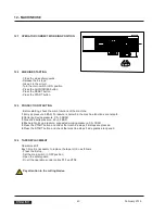
15.1


STATEMENT OF CONFORMITY


to the Directives on Machinery 2006/42 CE.


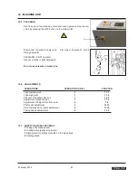
15.2


SAFETY LABELS


The safety labels are important for the correct use of the machine.


In case any label is damaged or removed, it is responsibily of the user to replace it immediately.


15.3


EMISSIONS OF RADIATIONS, GAS, VAPOURS AND DUST


Nothing to report


15.4


ELECTRIC TESTS


Electric tests:


1 - Continuity of the ground circuit 
2 - Insulation resistance


3 - High voltage insulation


Reference: EN 60204-1 Section 20.2, 20.3, 20.4


February 2016


51


   ENGLISH 


Summary of Contents for SM44 HS

Page 1: ...TIQUE AUTOMATISCHE KARTONVERSCHLIESSMASCHINE PRECINTADORA AUTOMATICA MANUALE DI ISTRUZIONI E PARTI DI RICAMBIO INSTRUCTIONS MANUAL AND SPARE PARTS LIST MANUAL D INSTRUCTIONS ET PIECES DETACHEES BEDIENUNGSANLEITUNG UND ERSTAZTEILLISTE MANUAL DE INSTRUCCIONES Y RECAMBIOS Cod pubbl SMB00087K 1 ...

Page 2: ... TURATE CO ITALY Tel 02 964951 Fax 02 9689727 Edition February 2016 The reproduction of this manual is strictly forbidden All rights reserved Siat S p A 2016 The manufacturer reserves the right to modify the product at any time without notice Publication n SMB00087K 1 Version 1 SM44 HS AUTOMATIC CASE SEALING MACHINE WITH DRIVE SIDE BELTS Maximum box size Minimum box size h 500 mm x w 500 mm x l 60...

Page 3: ...elt tension Additional Instructions Enclosures 1 1 1 2 3 2 1 2 2 2 3 3 6 4 2 4 6 5 6 7 8 9 10 11 12 12 3 12 4 12 7 13 13 5 13 9 13 10 13 11 14 15 Dwg Encl Ex Fig Max Min Mod N N A OFF ON OPP Pict PLC PP PTFE PVC Ref SIAT SPA drawing enclosure example figure showing spare parts maximum minimum machine model number not applicable machine stopped machine running oriented polypropylene adhesive tape p...

Page 4: ... damaged ask your after sale service for a new copy quoting the code num ber of the document CONSULTING THE MANUAL The manual is composed of 1 2 3 pages which identify the document and the machine index of the subjects instructions and notes on the machine sections 2 14 enclosures drawings and diagrams sections 15 16 spare parts last section All pages and diagrams are numbered The spare parts list...

Page 5: ...Via G Puecher N 22 Turate CO ITALY Watt Year Ampere Model Serial Number Hertz Type Volt Phase 2 2 FOR AFTER SALE SERVICE AND SPARE PARTS PLEASE APPLYTO February 2016 5 ENGLISH AGENT DISTRIBUTOR OR LOCAL AFTER SALE SERVICE Via Puecher 22 22078 TURATE CO ITALY Tel 02 964951 Fax 02 9682239 E mail siat siat com ...

Page 6: ...odging of Seller s personnel shall be sustainedbytheBuyer Buyerwillbe invoicedin conformitywithSeller sstandardchargesfortheservicesrendered Sellerisnotresponsiblefordefectsresultingfrom Improperuseofthemachine Lackofpropermaintenance TamperingwiththemachineorrepairseffectedbytheBuyer Seller will not be liable for any injury to personsor things or for the failure of production With respect to the ...

Page 7: ... in good and safe working condition 3 2 DEFINITION OF THE OPERATORS QUALIFICATIONS Machine operator Maintenance technician Electrician Manufacturer s technician Only persons who have the skills described in the following page should be allowed to work on the machine It is the responsibility of the user to appoint the operators having the appropriate skill level and the appropriate training for eac...

Page 8: ...k on live electrical panels connector blocks control equipment etc SKILL 3 SPECIALIST FROM THE MANUFACTURER Skilled operator sent by the manufacturer or its agent to perform complex repairs or modifications when agreed with the customer 3 3 INSTRUCTIONS FOR A SAFE USE OF THE MACHINE Only persons who have the skills described on the following paragraph 3 6 are allowed to work on the ma chine It is ...

Page 9: ...ODE OPERATOR S SKILL NUMBER OF OPERATORS Installation and set up of the machine Running with safety protections disabled 2 e 2a 2 Tape replacement Stopped by pressing the EMERGENCY STOP button 1 1 Replacement of blades Electric power disconnected 2 1 Replacement of drive belts Electric power disconnected 2 1 Ordinary maintenance Electric power disconnected 2 1 Extraordinary maintenance mecha nical...

Page 10: ...y sharp Any error may cause serious injuries WARNING Side flaps fold device guard knobs Don t remove the orange plastic guard knobs on the side flaps fold de vice ends 3 8 RECOMMENDATIONS AND MEASURES TO PREVENT OTHER HAZARDS WHICH CANNOT BE ELIMINA TED The operator must stay on the working position shown on paragraph 12 1 He must never touch the running driving belts or put his hands inside any c...

Page 11: ...or light detergents Do not use solvents petrochemicals etc Do not modify the machine or any part of it The manufacturer will not be responsible for anymodifications We advise to apply directly to Siat for modifications Follow carefully the installation instructions of this manual The manufacturer will notbe responsible for damages caused by improper installation 3 11 TABLE OF WARNINGS LABELS PLATE...

Page 12: ...ution High voltage f Label code 3 0 01100 96A g Tape threading path for upper taping unit Label code 3 0 01023 96A Compulsory position to lift the machine ktrucks or other suitable raising equipment with for h Labelcode SBC0010337 Identification data for the machine model serial num ber and manufacturer i Label code S340277700A 12 February 2016 ENGLISH SBC0010337 ...

Page 13: ...s K11 or K12 tape width 50 75 mm Machine control board AS24 weight 430 70 90 kg Compressed air 6 BAR feeding pipe diameter 10 mm Belts speed 30 m min Infeed conveyor speed 21 m min Air consumption 230 Nl min TAPE DIMENSIONS Suitable adhesive tapes PVC OPP ADHESIVE PAPER A 410 mm max B 50 75 mm C 76 mm 4 3 PURPOSE OF THE MACHINE The purpose of this machine is the sealing with adhesive tape of boxes...

Page 14: ...fed to the machine by the indexing unit AS24 The same indexing unit is equipped with a reading head for the identification of the format of the introduced box and the position of the following upper forming group correctly by appropriate electro pneumatic interface de vices The driving belts transport the box during the different phases from flaps folding to the following sealing to the exit of th...

Page 15: ...4 PRELIMINARYINFORMATION 4 7 OVERALL DIMENSIONS February 2016 15 ENGLISH ...

Page 16: ...m w width 980 mm h height 980 mm Weight 134 kg 5 2 PACKING FOR OVERSEAS SHIPMENT OPTIONAL The machines shipped by sea freight are covered by an aluminium po lyester Vacupol bag which contains dhydrating salts Machine packing machine 1 guards 3 accessories 4 Indexing unit packaging 5 3 STORAGE OF THE PACKED OR UNPACKED MACHINE In case the machine must stay inactive for a long period please take the...

Page 17: ...g up in order to free the machine 2 persons Move the machine and the infeed conveyor to where they will be lo cated Cut the stretch film and remove the guard panels and the accessories box Sealing machine brackets removal Caution the operations must be accomplished on all the four legs one at a time Remove the screws 1 Unscrew the nut 2 and remove the bracket Replace and tighten the screws 1 Actin...

Page 18: ...t or back side and remove the pallet Conveyor weight 90 kg 6 4 PACKING DISPOSAL The packing of the machine Mod SM44 HS is composed of wooden pallet carton box wooden supports steel fixing brackets polythene foam protection plastic straps PP clay dehydrating pouches aluminum polyester polythenebag only for seafreight shipments For the disposal of these materials please follow the provisions of the ...

Page 19: ...0 mm 7 3 SPARE PARTS AND THREADING TOOL FOR TAPING HEADS For a detailed description of the tools kit see section 13 1 7 4 MACHINE POSITIONING Raise the machine with a fork lift positioning the lift forks under the points where there are the labels 7 4 1 WORK HEIGHT ADJUSTMENT Lift the machine as shown in picture Unlock the screws and take the legs out looking for the desired con veyor bed height o...

Page 20: ...FETY GUARDS Support brackets upper and bottom 2 2 socket head screws each bracket 7 6 CONNECTION BETWEEN THE INDEXING UNIT AS24 AND THE MACHINE SM44 HS Lift the indexing unit by placing the forks under the points where the labels are 7 6 1 Move the indexing unit to the machine and fix it using the screws pre viously removed 7 6 2 Unlock the screws of the legs move the legs down to the floor and lo...

Page 21: ...centring guides cylinder connectors and to infeed conveyor cylinders Fitting acronyms shown in the picture identify the pipes number coming from the machine 5A 5B 7B 11A 11B 7 9 MAIN PNEUMATICCONNECTION Connect an air pipe to the ON OFF valve and fix it with a strap Min inside diameter of the pipe 10mm Air pressure 6 7 BAR Give air to the machine by the ON OFF valve February 2016 21 ENGLISH ...

Page 22: ...7 11 Carton sealer front box Box CA1 Cables n 3 and 6 CA2 CA1 Carton sealer front box Box CA2 Cable n 6 Connectors W70 SP1 Pressostat W73 Cylinder sensors W74 W77 Motor W78 22 February 2016 ENGLISH Cable n 6 Cable n 3 ...

Page 23: ...ton sealer rear box Cable n 5 Indexing unit box and vertical axes motors Cable n 4 Connectors W72 SQ32 W71 SQ30 SQ31 W8 Y Cylinder Cylinder sensor Cylinder W76 76 motor ground wire on the fixing screw February 2016 23 ENGLISH ...

Page 24: ...on of indexing unit photocells B10 B1 B2 Connect the photocells B10 B1 connector to the plug Connect the cables with connector coming from the machine to the pho tocells B2 B13 24 February 2016 ENGLISH B10 B1 B2 B13 B2 B10 B1 ...

Page 25: ...e mains voltage and fre quency meet the indications on the name plate of the machine 7 13 2Check that the connection of the machine to the mains meets the provisions of law and or the safety regulations in your country 7 14 MACHINE CONNECTION TO THE MAINS AND CHECK OUT Installed power 0 620 kW Connect the power cable A of the control board to an electric socket Standard power supply 400Volt 50 Hz ...

Page 26: ...OX 1 Centering guide pressure regulator 2 Side belts motorizations pressure regulator 3 Box height pick up pressure regulator WARNING In the box there s a pressure regulator of the compensation cylinder on the machine vertical axis dancer The regulator is adjusted by the manufacturer during ma chine assembly and testing 2 5 BAR the settled value should never be changed 26 February 2016 ENGLISH 3 2...

Page 27: ... in dexing unit plan follows and the re start of the corresponding motorization the machine works on the box Obscuring photocell n 2 activation of electronic control logic cycle start machine occupied Free photocell n 1 lowering of indexing unit drive belt with new photocell obscuring the following box will cause the stop of the corresponding motorization Obscuring photocell n 3 rear flap folder c...

Page 28: ...3 verify the lighting of the incorporated pilot lamp Wait for the lighting of the control panel 6 this is a touch screen panel so to activate a function or to move amoungst the pages it s enough to touch the screen with a finger on the corresponding text or pic tures Touch any point on the screen to enter the main page In case of alarm signalling in progress touch the corresponding symbol with a f...

Page 29: ...in menu mode A E Alarms page F Machine general reset G Page mode of manual machine axes drive H Page operation automatic cycle I Page of system settings and diagnostics I H G F E Press F reset Press Start button 5 obtaining in this way the rollers and the indexing unit belt start the motorizations start and the visualization of the operation automatic cycle page H on the control board 6 February 2...

Page 30: ...ling cycle on off lighting signalling Q Box upper sealing on off or transit without sealing re moving also the top taping unit R Alarms signalling tape end breakageon off S Only visualization tape end and full line A Page mode of manual machine axes drive G A Page of system settings and diagnostics I Warning Values are protected by passwords in order to avoid unauthorized changes that could to com...

Page 31: ...S 1 FIRST PHASE SPEED BOX SEARCH mm Low speed on box research AXIS 1 SECOND PHASE SPEED PROBE SLOWING mm Go up TI vert speed AXIS 1 RETURN TO HOME SPEED AFTER MEASURING mm Max value at height speed SPEED CHANGE HEIGHT MAX MIN mm Min value of box research MIN BOX HEIGHT ALARM TRIGGERED WITHOUT BOX mm Speed TO SM44 positioning AXIS 2 POSITIONING SPEED TAPING HEAD mm Go up TO vert speed AXIS 2 RETURN...

Page 32: ...ot executed 014 TI SQ08 not detected 016 Lower tape breakage 017 Upper tape breakage 018 Cycle max time 019 Alarm axis TI 020 Alarm axis TO 048 Lower tape end 049 Upper tape end 050 Full line B Reset B as necessary after intervention for the elimina tion of the problem that caused the alarm signalling Note in case of alarm signalling in positions 009 010 011 012 013 014 019 and 020 if the reset do...

Page 33: ...ed by safety covers on their external sides and by rigid elements on the exit side These protections must be im mediately replaced if damaged 10 4 EMERGENCY STOP BUTTONS The lockable emergency stop buttons are placed in handy position on control board and on the safty guards 10 5 ELECTRIC SYSTEM The electric system is protected by a ground wire whose continuity has been tested during the final ins...

Page 34: ... Attach the tape leg to the threading tool supplied with the tools kit Insert the plastic threading leader through the taping unit Take care to keep hands away from the tape cutting blades see section 3 11 b Follow the path through the unit as shown on picture and make sure that the adhesive side is placed on the correct side Pull and cut off the excess tape using a pair of scissors as shown 34 Fe...

Page 35: ... housing 11 3 TAPE DRUM ALIGNMENT Check the centering of the tape on the rollers of the taping unit If necessary unscrew the nut 1 and adjust the screw 2 11 4 TAPE DRUM FRICTION BRAKE ADJUSTMENT Check the tape tension with PVC the tape drum must be free with OPP the tape drum must be slightly frictioned 11 5 ADJUSTMENT OF TAPING UNITS ACCORDING TO THE TYPE OF BOXES Adjust the main spring decrease ...

Page 36: ...r with built in pressure gauge The pressure regulator 1 located on the front junction box adjusts the pressure of the centering guides of the infeedconveyor Working pressure 2 5 3 5 bar entry pressure 6 bar 4 6 60 80 100 40 2 8 20 120 140 bar psi 10 0 11 8 SIDE DRIVES PRESSURE ADJUSTMENT 2 Pressure regulator with built in pressure gauge The pressure regulator 2 located on the front junction box ad...

Page 37: ...s the pressure according to the board strength Decrease in case of light boxes Increase in case of strong boxes Minimum pressure must be adjusted so that the paddle returns auto matically in position once the box is passed 3 2 4 40 60 20 5 1 80 Working pressure 0 5 1 0 bar entry pressure 6 bar 0 bar psi 6 February 2016 37 ENGLISH 3 ...

Page 38: ...s closing speed unscrew the locking nut 3 turn the knob 4 clockwise to reduce the belts opening speed unti clockwise to increase the belts opening speed Centering guides opening closing speed regulators These are not common operations They have to be made only when it has been necessary to work on thepneumatic cylinder To change the speed do as follows 1 unscrew the locking nut 1 2 3 4 turn the kn...

Page 39: ...o as follows The speed of the rear flap folder unit can be akjusted by the flow regula tors mounted on the pneumatic cylinders It is necessary to introduce a screwdriver into the hole corresponding to theregulator 1 to adjust the descent speed of thearm 2 to adjust the ascent speed of thearm 3 to adjust the descent speed of the flapfolder 4 to adjust the ascent speed of the flap folder February 20...

Page 40: ...tions are not safe 2 Centering device pressure 2 5 3 5 BAR 3 Side drive belts pressure 2 3 3 5 BAR 4 Box height pick up pressure suggested working pressure 0 5 1BAR 5 Press the START button and check that machine stops if E stops are pressed 6 Press the START button and check that machine stops if side guards are opened 12 4 TAPE REPLACEMENT Operator skill 1 Each time it is necessary to replace th...

Page 41: ...water jets 12 6 ADJUSTMENTS OPERATIONS OPERATOR S SKILL CHAPTER Tape replacement Tape alignment Cheout of the safety devices Adjustment of tape tension Adjustment of height from floor level Photocells adjustment Side compressione rollers adjustment Taping heads adjustments 1 1 1 1 2 2 2 2 11 1 11 2 12 7 11 3 7 4 11 17 11 15 11 2 12 7 SAFETY DEVICES CHECKOUT 1 Taping units blade guard 2 Lockable em...

Page 42: ...on too loose Taping head idler rollers Check The length of the front tape leg on the box is not constat Adjust the tension Adjust Clean and lubricate the rollers Adhesive on blade Tape tension not enough Clean Increase the friction on the core hol der Replace The blade does not cut properly Springs on cutting lever not strong enough Blade damaged broken teeth Replace the blade Blade does not cut p...

Page 43: ...D FREQUENCY OF MAINTENANCE OPERATIONS 13 3 CHECKS TO BE PERFORMED BEFORE AND AFTER EVERY MAIN TENANCE OPERATION Alwayssetthemainswitchon 0 Off position Disconnecttheplugfromthemains During the maintenace operations only the operator performing the main tenancemustworkonthemachine Attheendofeverymaintenanceoperationcheckthatallsecuritiesandthe safety guards are working properly February 2016 43 ENG...

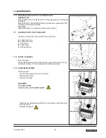
Page 44: ...es 4 Safety guards 13 5 MACHINE LUBRICATION Lubricate quarterly with grease Metal metal see paragraph 13 6 1 Slide cross bar ball guides for side drives grease nipples on the blocks 2 Columns upper unit cross bar ball guides grease nipples on the blocks 3 Side compression rollers ball guides grease nipples on the blocks 44 February 2016 ENGLISH 3 2 2 1 1 ...

Page 45: ...cture A B C D E spring holder pin spring tension pin roller shaft cutter hinge blade guard pin 13 8 13 9 BLADE CLEANING Skill 2 operator Lift the blade guard and clean the blade by using a brush with a long handle and some oil The oil prevents the adhesiveclotting BLADE REPLACEMENT Skill 2 operator Lift the blade guard as shown in Picture Release the screws Remove the blade WARNING Very sharp blad...

Page 46: ...y that both belts havethesamelevelofwear Remove theplug fromthemains andtake theairoffthecircuit DisconnecttheKlingelplugfromthesocket Loosen and remove the bolts that fix the connecting rod to the side flap folder Remove the side drives locking screws Removethesidedrive and placeitona workingtable 46 February 2016 ENGLISH OFF ...

Page 47: ...on covers Loosen the tensioning screws Releasethenutofthetensioningplate Removeandreplacethedrivebelt WARNING Before setting the new belt check the wear of the orange plastic rings on the drive pulleys replace them ifthey are worn out February 2016 47 ENGLISH ...

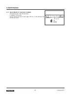
Page 48: ... 13 11 ADJUSTMENT OF THE BELTS TENSION Check the tension of the belt by pulling it outwards in themiddle A force of 3 5 kg should produce a gap of 25 mm 1 inch between the belt and the frame 48 February 2016 ENGLISH ...

Page 49: ...LIST OF THE MAINTENANCE OPERATIONS CARRIED OUT ON THE MACHINE Date Description of operation February 2016 49 ENGLISH ...

Page 50: ...steel frame nylon conveyor rollers PVC drive belts nylon pulleys Inorderto disposeof theabovematerials pleasecomplywiththelawinforcein your country 14 2 INSTRUCTIONS ON EMERGENCY SITUATIONS In case of danger fire disconnect the electric power FIRE IncaseoffireuseanextinguishercontainingCO2 DONOTusewater 50 February 2016 ENGLISH ...

Page 51: ...ofthemachine Incaseanylabelisdamagedorremoved itisresponsibily oftheusertoreplaceitimmediately 15 3 EMISSIONS OF RADIATIONS GAS VAPOURS AND DUST Nothing to report 15 4 ELECTRIC TESTS Electric tests 1 Continuity ofthegroundcircuit 2 Insulationresistance 3 Highvoltageinsulation Reference EN60204 1Section20 2 20 3 20 4 February 2016 51 ENGLISH ...

Page 52: ......

Page 53: ...E AUTOMATIQUE AUTOMATISCHE KARTONVERSCHLIESSMASCHINE PRECINTADORA AUTOMATICA PARTI DI RICAMBIO SPARE PARTS LIST PIECES DETACHEES ERSTAZTEILLISTE RECAMBIOS SIATS p A Via Puecher 22 22078 TURATE CO ITALY P O BOX 1 Tel 02 964951 Telefax 02 9689727 http www siat com E Mail siat siat com ...

Page 54: ...bancale 19 PZ S340072093Z Vite testa mezza tonda M5X12 croce zincata 20 PZ S4510004947A Canalina inf bancale c inserti 21 PZ S4510003247A Carter inferiore bancale c inserti 22 PZ S340057793Z Vite TCEI M6X16 zincata 23 PZ S340017593Z Rondella piana per vite M6 zincata 24 PZ S3210009547A Piastrina carter inf bancale 25 PZ S320804247A Staffa per passalamiera SM44 26 PZ S340003393Z Rondella tripla per...

Page 55: ......

Page 56: ...e TCEI M10X20 zincata 16 PZ S4410002147A Piastra laterale guida mot c perno 17 PZ S340017593Z Rondella piana per vite M6 zincata 18 PZ S3310004593A Forcella sinistrorsa 19 PZ S3310004493A Forcella destrorsa 20 PZ S3310004393A Giunto catena 21 PZ S330560293Z Vite tendicatena dx sx SM4 F 104 22 PZ S340004593Z Vite TE M5X20 zincata 23 PZ S340025993Z Dado autobloccante M5 zincato 24 PZ S340006193Z Ron...

Page 57: ...14 15 38 13 16 8 29 34 30 35 28 15 17 17 7 12 33 31 9 37 36 32 27 11 21 18 19 1 22 26 3 11 10 20 23 24 26 2 4 5 6 7 SM44 HS Fig 15390 Giu 2010 ...

Page 58: ...M M3 4 I Festo 10 PZ S310175300A Pressatore laterale SM8 P 11 PZ S350207593Z Perno per rulli pressatori 700A 12 PZ S330535393Z Rondella 8 5X25X4 13 PZ S340028093Z Vite TE M8X20 zincata 14 PZ S340065593Z Rondella tripla per vite M8 zincata 15 PZ S3801683ZZZ Raccordo Y LEGRIS31400600 16 PZ S340507793A Vite TBEI M8X20 zincata 17 PZ S4310000100A Biella c cuscinetto e ammortizz 18 PZ S4410002747A Biell...

Page 59: ...5 3 4 25 4 7 8 26 15 13 16 14 9 1 2 24 12 12 20 5 23 14 10 18 17 5 11 22 6 19 21 SM44 HS Fig 15391 Giu 2010 ...

Page 60: ...0000693Z Rondella dentellata per vite M6 22 PZ S330535693Z Vite TE M6X12 spec 23 PZ S340002193Z Vite TE M6X12 zincata 24 PZ S340017593Z Rondella piana per vite M6 zincata 25 PZ S340101093Z Testa a snodo M10X1 25 zincata 26 PZ S3210014447A Squadretta per molla a bandella 27 PZ S320157784B Prolunga chiudifalda post SM44 28 PZ S340072093Z Vite testa mezza tonda M5X12 croce zincata 29 PZ SBA0010149 Ca...

Page 61: ... 26 45 24 44 47 48 49 42 19 41 23 27 23 10 35 36 33 12 19 40 11 19 34 10 39 31 32 31 37 38 30 SM44 HS Fig 15392 Giu 2010 5 6 7 8 21 20 4 3 18 42 13 3 14 42 13 18 18 19 19 18 24 16 16 17 23 24 2 19 15 25 16 22 9 22 24 23 9 ...

Page 62: ...con insertiHM11 T 21 PZ S320580617A Piastrina di chiusura HM11 T 22 PZ S340072093Z Vite testa mezza tonda M5X12 croce zincata 23 PZ S340002393Z Dado M5 zincato 24 PZ S340006193Z Rondella piana per vite M5 zincata 25 PZ S3210011547A Squadretta fissaggio blocco a scatto 26 PZ S3210011347A Squadretta fissaggio sportello 27 PZ S3210011247A Squadretta interruttore di sic 28 PZ S340031893Z Vite TCEI M5X...

Page 63: ......

Page 64: ...HS 4 PZ SBC0014869V Carter spalla porta unita AS24 HS 5 PZ S330892993Z Distanziale 10X10X150 6 PZ S332586695A Bloc destro fissaggio K13 TOP 120af 3M 7 PZ S332586795A Bloc sx fissaggio K13 TOP 120af 3M 8 PZ S340037193Z Vite TE M5X12 zincata 9 PZ S340006193Z Rondella piana per vite M5 zincata 10 PZ S340017593Z Rondella piana per vite M6 zincata 11 PZ S340002693Z Vite TE M6X16 zincata 12 PZ S34000579...

Page 65: ...11 11 12 8 1 10 5 10 2 4 10 5 10 14 6 11 10 1 7 14 10 9 8 13 10 11 3 12 10 SM44 HS Fig 15394 Giu 2010 ...

Page 66: ...ription Descrizione Prodotto Nastratrice Posizione Unità mis Codice SIAT Definizione 3 PZ S330628493Z Distanziale 12X12X140 SM11 zincato 4 PZ S340002193Z Vite TE M6X12 zincata 5 PZ S340017593Z Rondella piana per vite M6 zincata 6 PZ S340058493Z Vite TCEI M8X16 zincata 7 PZ S340012393Z Rondella piana per vite M8 zincata ...

Page 67: ...5 4 3 4 5 6 7 SM44 HS Fig 15395 Sett 2013 ...

Page 68: ......

Page 69: ......

Page 70: ...Z Anello arresto per albero 20 brunito 22 PZ S340044592Z Anello arresto per foro 42 brunito 23 PZ S340028393Z Dado autobloccante M8 basso zincato 24 PZ S340065593Z Rondella tripla per vite M8 zincata 25 PZ S470405200A Puleggia doppia ass SM11 48 26 PZ S4503371ZZZ Puleggia di rinvio SM11 27 PZ S3400193ZZZ Cuscinetto 6000 2RS 28 PZ S3400095A Cuscinetto 6203 2RS 29 PZ S330596292Z Perno per puleggia r...

Page 71: ... 63 59 53 54 56 57 55 58 5 6 82 5 45 23 24 89 81 86 34 4 47 46 5 6 87 3 62 21 49 50 40 41 48 15 8 65 43 64 25 33 4 39 6 5 6 85 88 17 24 90 24 23 2 61 42 44 32 31 35 34 76 91 95 67 75 39 64 65 83 6 84 94 SM44 HS Fig 15396 1 Giu 2010 80 79 77 78 92 93 91 ...

Page 72: ...Z S3210018300A Scivolo superiore dx motorizz 67 PZ S3210018200A Scivolo inferiore motorizzazioni 68 PZ 69 PZ 70 PZ S3803441ZZZ MOT H63A4 220V 240V 380 415V 50H 0 13KW 71 PZ SCA0000213 Tappo in plastica serie Heyco 72 PZ 73 PZ 74 PZ 75 PZ 76 PZ S3210018400A Scivolo superiore sx motorizzazioni 77 PZ S3801458ZZZ Custodia vol uscita verti PG11 105121 78 PZ S3801455ZZZ Inserto maschio 4 POLI 3P T 79 PZ...

Page 73: ...SM44 HS Fig 15396 2 Giu 2010 17 21 22 20 18 19 25 29 26 30 26 27 28 15 11 16 11 14 13 35 38 36 37 9 10 8 11 12 9 11 14 13 ...

Page 74: ...Cassetta impianto pneum c inserti 8 PZ S4510003647A Sportello scatola imp pneum c inserti 9 PZ S3402920ZZZ Serratura SOUTHCO E5 2 015 111 WS3 10 PZ S340215405Z Gomma spugnaF144 11 PZ S4510003447A Piastrina fissaggio sportello c inserti 12 PZ S340398000A Cer ELESA CFA 65 CH 6 COD 422232 SM 13 PZ S340057793Z Vite TCEI M6X16 zincata 14 PZ S3210010847A Supporto regolatori di flusso 15 PZ S340057793Z V...

Page 75: ...5 20 4 1 19 17 5 2 3 9 6 5 14 18 19 9 7 11 12 16 15 13 10 8 SM44 HS Fig 15397 Giu 2010 ...

Page 76: ...S340057793Z Vite TCEI M6X16 zincata 13 PZ S340003393Z Rondella tripla per vite M6 zincata 14 PZ S3802388ZZZ Finecorsa di safety con staff per 800af 15 PZ S3802139ZZZ Bocchettone skintop ST11 16 PZ S340011293Z Vite TCEI M5X16 zincata 17 PZ S4710002700A Rullo completo L 650 SM44 18 PZ S4710002500A Rullo assemblato L 650 19 PZ SBC0008965T Perno per rullo L 650 SM44S 20 PZ S340102492Z Anello arresto 1...

Page 77: ......

Page 78: ...ta con ins 12 PZ SBA0009413V Traversa inferiore colonna 13 PZ S340001593Z Vite TCEI M6X25 zincata 14 PZ SCA0000771 Rotaia guida lineare MOD HRS25 320LG 15 PZ SBA0009452 Traversa sup chiudifalda c ins SM44HS 16 PZ S340058493Z Vite TCEI M8X16 zincata 17 PZ S340048693Z Vite TCEI M8X25 zincata 18 PZ S3310004000A Blocchetto fissaggio traversa 19 PZ SCA0000769 Pattino per guida lineare MOD HRS25ASSG 20 ...

Page 79: ...2 24 21 23 25 22 11 27 26 20 5 1 18 16 9 5 17 5 10 5 9 15 28 29 14 30 13 8 12 7 5 5 6 4 1 2 3 SM44 HS Fig 15399 Giu 2010 9 ...

Page 80: ...3593Z Dado M12 autobloccante 13 PZ S340125893A Dado autobloccante M16 zincata 14 PZ S340142093Z Rondella piana per vite M16 zincata 15 PZ S340101693Z Testa a snodo M12X1 25 zincata 16 PZ S3310003992A Perno sup attacco cilindro 17 PZ S340021993Z Rondella piana per vite M10 zincata 18 PZ S340043893Z Dado autobloccante M10 basso 19 PZ SCC0002042 Servomotore junma freno 400W 20 PZ S340010893Z Vite TCE...

Page 81: ...18 17 12 14 13 16 15 10 10 11 10 9 9 2 1 2 3 8 7 1 2 2 3 6 4 5 6 4 SM44 HS Fig 15400 1 Giu 2010 ...

Page 82: ...3593Z Dado M12 autobloccante 13 PZ S340125893A Dado autobloccante M16 zincata 14 PZ S340142093Z Rondella piana per vite M16 zincata 15 PZ S340101693Z Testa a snodo M12X1 25 zincata 16 PZ S3310003992A Perno sup attacco cilindro 17 PZ S340021993Z Rondella piana per vite M10 zincata 18 PZ S340043893Z Dado autobloccante M10 basso 19 PZ SCC0002042 Servomotore junma freno 400W 20 PZ S340010893Z Vite TCE...

Page 83: ...27 27 25 24 24 25 7 24 22 22 23 22 21 20 19 SM44 HS Fig 15400 2 Giu 2010 30 31 31 28 29 28 8 26 ...

Page 84: ......
Reviews: