background image

- 78 -

&

&

&

&

&


Save  & Exit Setup

Pressing <Enter> on this item asks for confirmation:

           Save to CMOS and EXIT (Y/N)?  Y

Pressing "Y" stores the selections made in the menus of CMOS - a
special section of memory that stays on after you turn your system off.
The next time you boot your computer, the BIOS configures your
system according to the Setup selections stored in CMOS. After saving
the values the system is restarted again.

&

&

&

&

&


Exit Without Saving

Pressing <Enter> on this item asks for confirmation:

           Quit without saving (Y/N)?  Y

This allows you to exit from Setup without storing in CMOS any
change.  The previous selections remain in effect.  This exits from the
Setup utility and restarts your computer.

Summary of Contents for MB47N

Page 1: ...MB47N Pentium 4 Celeron 478 Pin Processor Based MAIN BOARD User s Manual...

Page 2: ...ully checked for reliability however no guarantee is given as to the correctness of the contents In the interest of continued product improvement this company reserves the right to revise the manual o...

Page 3: ...onnect Front Panel Switches LEDs Speaker USB AUDIO1 14 STEP 7 Connect IDE and Floppy Disk Drives 16 STEP 8 Connect Other Internal Peripherals 16 STEP 9 Connect the Power Supply 17 STEP 10 Install Add...

Page 4: ...ME MIDI Port Connector 28 Front Panel Connectors Speaker Connector SPEAKER 30 Panel1Connector 30 Audio1Connector 31 Extend USB Header USB2 USB3 31 Internal Peripherals Connectors Enhanced IDE and Flop...

Page 5: ...nstall LAN Driver 43 4 8 View the User s Manual 49 5 BIOS SETUP 50 5 1 ENTER BIOS 50 5 2 THE MAIN MENU 51 STANDARD CMOS FEATURES 53 ADVANCED BIOS FEATURES 55 ADVANCED CHIPSET FEATURES 58 INTEGRATEDPER...

Page 6: ...th containing MB47N user s manual saved in PDF format Intel Chipset System Driver Onboard Audio controller driver IDE driver USB2 0 Driver VGA driver Award Flashing Utility 1INTRODUCTION 1 R T L 810 0...

Page 7: ...B and data bandwidths up to 3 2GB s AC 97 Link for 4 Channel Audio and Telephony CODEC AC 97 audio codec is compliant with the AC 97 2 3 specification and supports 18 bit ADC Analog Digital Converter...

Page 8: ...API Devices ATAPI IDE CD ROM CD R CD RW and LS 120 Supports ATX Power Supply Connector ATX power supply unit can connected to the onboard 20 pin Pentium 4 standard ATX power connectors supporting Susp...

Page 9: ...lock Setting This item allows users to adjust CPU Host Clock in BIOS CPU Multiplier Setting CPU Multiplier Setting CPU Multiplier Setting CPU Multiplier Setting CPU Multiplier Setting This item allows...

Page 10: ...entify various jumpers connectors slots and ports Then follow these steps designed to guide you through a quick and correct installation of your system 3 1 Step by Step Installation 3 HARDWARE INSTALL...

Page 11: ...installation Be careful of CPU orientation when you plug it into CPU socket 1 Pull up the CPU socket level and up to 90 degree angle 2 Locate Pin 1 in the socket and look for a black dot or cut edge o...

Page 12: ...10 3 Press down the CPU socket level and finish CPU installation Note Note Note Note Note If you do not match the CPU socket Pin 1 and CPU cut edge well it may damage the CPU...

Page 13: ...e factory set default settings are tuned for opti mum system performance For the advanced users who wish to customize their system section 3 2 Jumper Settings 3 2 Jumper Settings 3 2 Jumper Settings 3...

Page 14: ...vice according to the instructions provided by the manufacturer IDE devices HDD and CD ROM have to set jumpers to Master or Slave mode depending on whether you install more than one device of each kin...

Page 15: ...ainboard The studs are used to fix the mainboard and to keep a certain distance between the system chassis and the mainboard in order to avoid any electrical shorts between the board and the metal fra...

Page 16: ...the front panel switches LEDs and USB connectors to the mainboard front panel connectors group PANEL1 USB2 3 SPEAKER1 AUDIO1 as shown below 1 HDD LED 2 Green LED Indicator 3 Reset Switch 4 Power ON O...

Page 17: ...SBP3 23 GROUND 24 NC SPEAKER1 1 SIGNAL 2 KEY 3 Ground 4 VCC AUDIO 1 1 MICIN 2 AGND 3 MICBIAS 4 5V 5 SPKOUTR 6 XSPKOUTR 7 KEY 8 EMPTY 9 SPKOUTL 10 XSPKOUTL 1 SPEAKER 1 4 3 2 1 AUDIO1 1 1 3 5 7 9 2 4 6...

Page 18: ...16 CD IN 1 CD IN 2 Step 7 Connect IDE and Floppy Disk Drives 1 IDE cable connector 2 Floppy cable connector Step 8 Connect Other Internal Peripherals 1 CD IN1 CD IN2 connectors 1 FDDI IDE1 IDE2 1 1 1...

Page 19: ...17 Step 9 Connect the Power Supply 1 System power connector Step 10 Install Add on Cards in Expansion Slots 1 PCI Card 2 CNR Card ATX 12V ATX 1...

Page 20: ...to put the computer case back together and get on to the external peripherals connections to your system back panel 1 PS 2 Mouse and PS 2 Keyboard 2 Parallel Port 3 COM Port 4 VGA Port 5 MIDI GAME Por...

Page 21: ...ill display the drivers main installation window on screen 2 Choose Install Chipset System Driver and complete it 3 Choose Install Intel Ultra ATA Driver and complete it 4 Choose Install Intel USB2 0...

Page 22: ...umpers with two pins are shown as for Close On or for Open Off To Short jumper pins simply place a plastic mini jumpers over the desired pair of pins Caution Caution Caution Caution Caution 1 Do not r...

Page 23: ...rs slots and connec tors along with their assigned functions CPU Memory Expansion Slots Socket478 CPU Socket for Pentium4 Celeron 478 pin processors DIMM1 2 Two DIMM Slots for 128 256 512 MB and 1GB o...

Page 24: ...port LINE_OUT Line Out port LINE_IN Line In port MIC_IN Mic In port GAME MIDI GAME MIDI Port Front Panel Connectors SPEAKER Internal speaker in housing PANEL1 PANEL connector AUDIO1 Front Panel MIC Sp...

Page 25: ...SFAN Chassis fan connector IR1 Infrared cable header WOM1 Wake On Modem wake up connector WOL1 Wake On LAN wake up connector CDIN1 CD_IN connector WHITE Panasonic Type CDIN2 CD_IN connector BLACK Sony...

Page 26: ...Step 3 Step 3 Step 3 Step 3 Remove jumper cap from JP1 pins 1 2 Step 4 Step 4 Step 4 Step 4 Step 4 Place the jumper cap on JP1 pin 2 3 for a few seconds Step 5 Step 5 Step 5 Step 5 Step 5 Return the j...

Page 27: ...ltage Selector Jumper Setting VID4 VID0 VID4 VID0 is used to set the CPU voltage manually to improve the CPU performance However don t change the VID4 VID0 setting if you aren t familiar with the CPU...

Page 28: ...1 375 open 2 3 close 2 3 close open 2 3 close 1 400 open 2 3 close 2 3 close 2 3 close open 1 425 open 2 3 close 2 3 close 2 3 close 2 3 close 1 450 2 3 close open open open open 1 475 2 3 close open...

Page 29: ...ks into their corresponding connectors LAN Port Connector This mainboard can accommodate one de vice on LAN Attach RJ 45 cable to this port connect to your PC to the LAN LAN Port Connector This mainbo...

Page 30: ...1 8 inch TRS stereo headphones or to amplified speakers Line In Port Connector Line In is a stereo line level input port that ac cepts a 1 8 inch TRS stereo plug It can be used as a source for digita...

Page 31: ...nection MIDI Instrument Connection You will need a MIDI adapter to connect a MIDI compatible instrument to the sound card The MIDI adapter can in turn be connected to the Joystick MIDI port You will a...

Page 32: ...R Panel1 Connector The panel1 connector provides a standar set of switch and LED connectors commonly found on ATX or micro ATX cases 1 HDD LED 2 Green LED Indicator 3 Reset Switch 4 Power ON OFF 1 SPE...

Page 33: ...panel please remove all jumpers from PANEL1 and install your special Extra Mic Line out cable instead AUDIO1 1 Extend USB Header USB2 USB3 This headers are used to connect the cable attached to USB co...

Page 34: ...es one 34 pin floppy disk controller FDD1 to accommodate the Floppy Disk Drive FDD Moreover this mainboard comes with one 80 pin ATA 100 66 33 100 66 33 100 66 33 100 66 33 100 66 33 ribbon cable to c...

Page 35: ...solve this problem You may enable the function PWRON After PWR Fail that is under sub menu of Power Management Setup through BIOS setup program Note 1 Note 1 Note 1 Note 1 Note 1 The ATX power connect...

Page 36: ...ment IR transfer function To enable the IR transfer function follow these steps Note Note Note Note Note Before connect your IR1 device please be sure each IR1 on board pin allocation is matchable wit...

Page 37: ...5VSB 2 Ground 3 Wake_up Wake On LAN Connector WOL1 Attach a 3 pin connector through the LAN card which supports the Wake On LAN WOL1 function This function lets users wake up the connected system thro...

Page 38: ...ry automatically You can check the total system memory value in the BIOS Standard CMOS Setup menu 2 Upgrade Memory You can easily upgrade the system memory by inserting additional DDR SDRAM modules in...

Page 39: ...r Description Navigation Bar Description Install Mainboard MB47N Software Install Mainboard MB47N Software Install Mainboard MB47N Software Install Mainboard MB47N Software Install Mainboard MB47N Sof...

Page 40: ...up screen Select using your pointing device e g mouse on the Install Mainboard Install Mainboard Install Mainboard Install Mainboard Install Mainboard MB47N Software MB47N Software MB47N Software MB47...

Page 41: ...nstall INTEL INF Install INTEL INF Install INTEL INF Driver Driver Driver Driver Driver bar to install INTEL INF driver Once you made your selection a Setup window run the installation automatically W...

Page 42: ...ra Install Intel Ultra Install Intel Ultra ATA Driver ATA Driver ATA Driver ATA Driver ATA Driver bar to install Ultra ATA IDE driver Once you made your selection a Setup window run the installation a...

Page 43: ...GA Driver Select using your pointing device e g mouse on the Install VGA Device Install VGA Device Install VGA Device Install VGA Device Install VGA Device Driver Driver Driver Driver Driver bar to in...

Page 44: ...dio De Install Audio De Install Audio De vice Driver vice Driver vice Driver vice Driver vice Driver bar to install Audio driver Once you made your selection a Setup window run the installation automa...

Page 45: ...river please confirm your OS and correctly install driver If your OS is Win 9X NT please take correctly install driver If your OS is Win 9X NT please take correctly install driver If your OS is Win 9X...

Page 46: ...lect tab Device Manager You will find a yellow mark at PCI Ethernet Controller that means the driver is not recognize Double click on the Ethernet Control ler Then PCI Ethernet Controller Prop erties...

Page 47: ...l driver and click on Next bar to continue Select Network adapters bar for LAN device and click on Next bar to continue Insert the support CD by the mainboard manufacturer and choose Have Disk bar to...

Page 48: ...8139 A B Realtek RTL8139 A B Realtek RTL8139 A B C 8130 PCI Fast Ethernet NIC C 8130 PCI Fast Ethernet NIC C 8130 PCI Fast Ethernet NIC C 8130 PCI Fast Ethernet NIC C 8130 PCI Fast Ethernet NIC driver...

Page 49: ...er Insert the support CD by the mainboard manufacturer and choose Have Disk Have Disk Have Disk Have Disk Have Disk bar to continue next step Key in the driver s location as D lan WINNT4 D lan WINNT4...

Page 50: ...altek RTL8139 A B C 8130 PCI Fast Ethernet Adapter 8130 PCI Fast Ethernet Adapter 8130 PCI Fast Ethernet Adapter 8130 PCI Fast Ethernet Adapter 8130 PCI Fast Ethernet Adapter driver and click on Close...

Page 51: ...n Online Information Online Information Online Information windows will appear on your screen Click on the Install Acrobe Reader Install Acrobe Reader Install Acrobe Reader Install Acrobe Reader Insta...

Page 52: ...ess DEL to enter SETUP or simultaneously press Ctrl Alt Esc keys Note 1 Note 1 Note 1 Note 1 Note 1 If you miss trains of words meationed in step2 the message disappears before you can respond and you...

Page 53: ...up Items The main menu includes the following main setup categories Recall that some systems may not include all entries Standard CMOS Features This menu displays the basic information about your syst...

Page 54: ...ail safe defaults for all appropriate items in the setup utility Load Optimized Defaults Use this menu to install optimized defaults for all appropriate items in the setup utility Set Supervisor User...

Page 55: ...ms are automatically updated whenever you make changes to the Windows Date Time Time Time Time Time HH MM SS Set the system time The time is converted based on the 24 hour military time clock For exam...

Page 56: ...2MB Floopy 3 mode is sometimes used in Japan The choice Disabled Drive A Drive B Both Video EGA VGA Video EGA VGA Video EGA VGA Video EGA VGA Video EGA VGA This item define the video mode of the syst...

Page 57: ...ick Power On Self Test Enabled Enable this item to shorten the power on testing POST and have your system start up faster You might like to this item after you are confident that your system hardware...

Page 58: ...Status ON Boot Up NumLock Status ON Boot Up NumLock Status ON Boot Up NumLock Status ON Boot Up NumLock Status ON This item defines if the keyboard Num Lock key is active when your system is started...

Page 59: ...Select For DRAM 64MB Non OS2 OS Select For DRAM 64MB Non OS2 OS Select For DRAM 64MB Non OS2 OS Select For DRAM 64MB Non OS2 This item is only required if you have installed more than 64 MB of memory...

Page 60: ...e installed memory chips DRAM Don t change the value from the factory setting unless you install new memory that has a different perfor mance rating than the original DRAMs The Choice Manual or By SPD...

Page 61: ...Memory Frequency For This item select SDRAM Frequency The Choice PC100 PC133 or Auto System BIOS Cacheable System BIOS Cacheable System BIOS Cacheable System BIOS Cacheable System BIOS Cacheable Selec...

Page 62: ...P Aperture Size MB 128 AGP Aperture Size MB 128 AGP Aperture Size MB 128 AGP Aperture Size MB 128 This item defines the size of the aperture if you use an AGP graphics adapter The AGP aperture refers...

Page 63: ...Primary Master Primary Slave Secondary Master Secondary IDE Primary Master Primary Slave Secondary Master Secondary IDE Primary Master Primary Slave Secondary Master Secondary IDE Primary Master Prim...

Page 64: ...abled USB Keyboard Support Disabled USB Keyboard Support Disabled USB Keyboard Support Disabled Select Enabled if you plan to use a keyboard connected through the USB port in a legacy operating system...

Page 65: ...nly Keyboard 98 KB Power ON Password Enter KB Power ON Password Enter KB Power ON Password Enter KB Power ON Password Enter KB Power ON Password Enter When the POWER ON Function is set to Password use...

Page 66: ...s you to set the IR reception transmission polarity as High or Low The choice Hi Hi Hi Lo Lo Hi Lo Lo IR Transmission Delay Enabled IR Transmission Delay Enabled IR Transmission Delay Enabled IR Trans...

Page 67: ...7 EPP Mode Select EPP1 7 The onboard parallel port is EPP spec compliant after you choose the onboard parallel port with EPP function Set the EPP version to 1 7 spec or 1 9 spec The choice EPP1 9 or...

Page 68: ...POS ACPI Suspend Type SI POS ACPI Suspend Type SI POS This item allows you to select sleep state when suspend In the default S1 POS the suspend modeis equivalent to a software power down If you selec...

Page 69: ...Yes Video Off In Suspend Yes Video Off In Suspend Yes Video Off In Suspend Yes Video Off In Suspend Yes This item defines if the video is powered down when the system is put into suspend mode The cho...

Page 70: ...down The choice Instant Off or Delay 4 Sec CPU Thrm Throttling 50 0 CPU Thrm Throttling 50 0 CPU Thrm Throttling 50 0 CPU Thrm Throttling 50 0 CPU Thrm Throttling 50 0 Use this item to specify the CP...

Page 71: ...ry Secondary IDE 0 1 Disabled Primary Secondary IDE 0 1 Disabled Primary Secondary IDE 0 1 Disabled Primary Secondary IDE 0 1 Disabled Primary Secondary IDE 0 1 Disabled When these items are enabled t...

Page 72: ...ta Disabled Reset Configuration Data Disabled If you enable this item and restart the system any Plug and Play con figuration data stored in the BIOS Setup is cleared from memory The choice Enabled or...

Page 73: ...I VGA Palette Snoop Disabled PCI VGA Palette Snoop Disabled PCI VGA Palette Snoop Disabled PCI VGA Palette Snoop Disabled This item is designed to overcome problems that can be caused by some non stan...

Page 74: ...49 C F 70 C C 158 C F 75 C C 167 C F CPU Warning Tempertuare CPU Warning Tempertuare CPU Warning Tempertuare CPU Warning Tempertuare CPU Warning Tempertuare Use this item to set the warning temperatur...

Page 75: ...onent Characteristics These fields provide you with information about the systems current operating status You can t make changes to these fields System Temp system temperature CPU temp CPU temperatur...

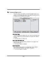
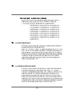
Page 76: ...st PCI Clock should equal the core speed of the installed processor The choice Min 8 or Max 50 Auto Detect DIMM PCI Clk Auto Detect DIMM PCI Clk Auto Detect DIMM PCI Clk Auto Detect DIMM PCI Clk Auto...

Page 77: ...ress N and then Enter to not install the defaults The fail safe defaults place no great demands on the system and are generally stable If your system is not functioning correctly try installing the fa...

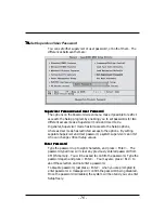
Page 78: ...etup options whereas User mode has restricted access to the options By setting separate Supervisor and User password a system supervisor can limit who can change critical Setup values Enter Password E...

Page 79: ...password whenever the system is rebooted or you try to enter Setup If you select Setup at Security Op tion of BIOS Features Setup Menu you will be prompted only when you try to enter Setup Warning War...

Page 80: ...ext time you boot your computer the BIOS configures your system according to the Setup selections stored in CMOS After saving the values the system is restarted again Exit Without Saving Pressing Ente...

Reviews: