background image

- 72 -

@

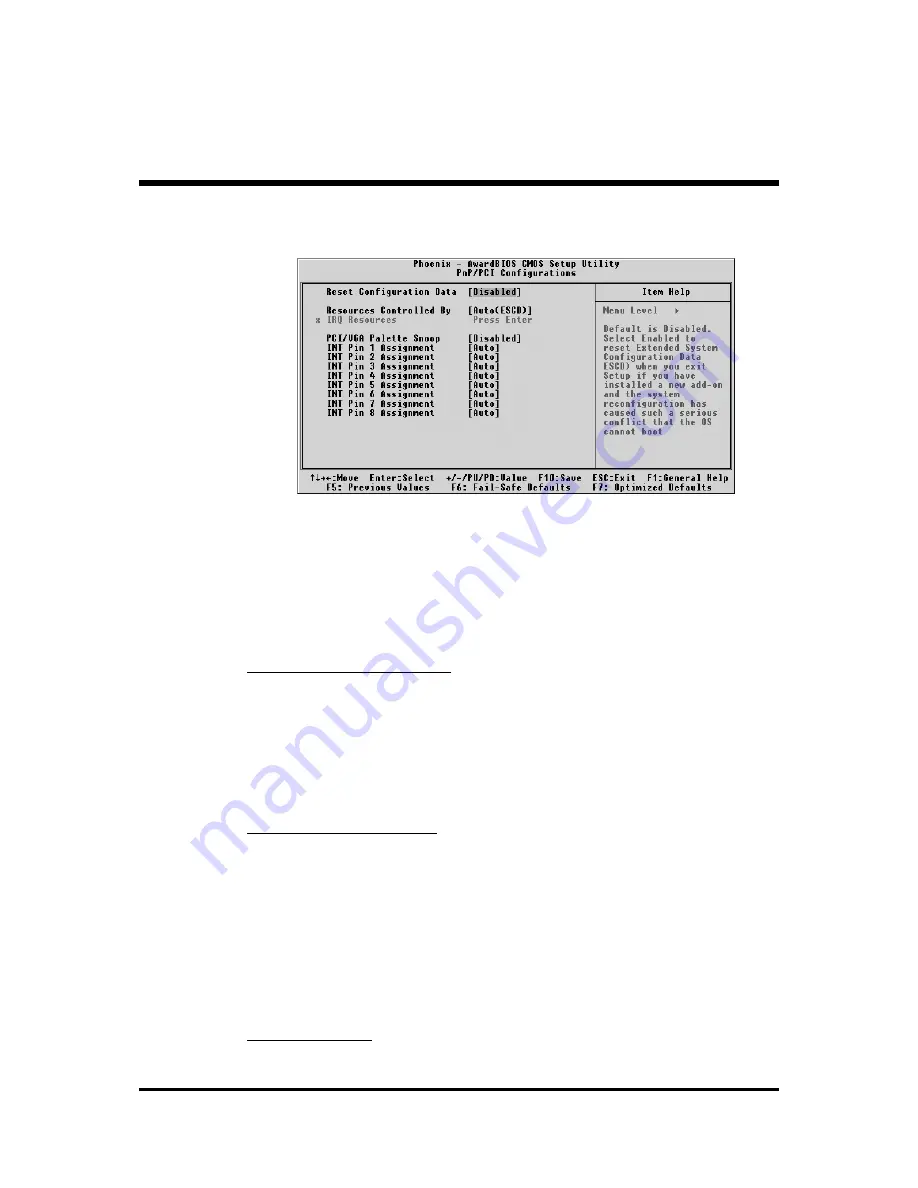
PnP/PCI Configurations

This section describes the configuration of PCI bus system.  PCI or

Personal Computer Interconnection is a system which allows I/O

devices to operate at the speed CPU itself keeps when CPU

communicating with its own special components.

This section covers some very technical items, and it is strongly

recommended that only experienced users should make any

changes to the default settings.

Reset Configuration Data

Reset Configuration Data

Reset Configuration Data

Reset Configuration Data

Reset Configuration Data

Normally, you leave this field Disabled.  Select Enabled to reset

Extended System Configuration Data (ESCD) when you exit from Setup

if you have installed a new device or software and the system

reconfiguration has caused such a serious conflict that the operating

system can not boot.

Ø

The choice: Enabled or Disabled .

Resource controlled By

Resource controlled By

Resource controlled By

Resource controlled By

Resource controlled By

The Award Plug-and-Play BIOS has the capacity to automatically

configure all of the boot and Plug-and-Play compatible devices.

However, this capability means absolutely nothing unless you are using

a Plug-and-Play operating system such as Windows 95.
If you set this field to "manual" , choose specific resources by going into

each of the sub-menu that follows this field (a sub-menu is proceeded

by a ">").

Ø

The choice: Auto(ESCD) or Manual.

IRQ  Resources

IRQ  Resources

IRQ  Resources

IRQ  Resources

IRQ  Resources

When resources are controlled manually, assign each system interrupt a

type, depending on the type of device using the interrupt.

Summary of Contents for FB51

Page 1: ...FB51 Pentium 4 Celeron 478 pin Processor Based MAIN BOARD ...

Page 2: ...fully checked for reliability however no guarantee is given as to the correctness of the contents In the interest of continued product improvement this company reserves the right to revise the manual or include changes in the specifications of the product described within it at any time without notice and without obligation to notify any person of such revision or changes The information contained...

Page 3: ...allation 12 STEP 2 Set Jumpers 14 STEP 3 Install DDR SDRAM System Memory 14 STEP 4 Install Internal Peripherals in System Case 15 STEP 5 Mount the Mainboard on the Computer Chassis 16 STEP 6 Connect Front Panel Switches LEDs Speaker USB 17 STEP 7 Connect IDE and Floppy Disk Drives 19 STEP 8 Connect Other Internal Peripherals 19 STEP 9 Connect the Power Supply 20 STEP 10 Install Add on Cards in Exp...

Page 4: ...or 30 Line Out Front Out Port Connector 30 Line In Rear Out Port Connector 31 SPDIF_ In Port 31 Front Panel Connectors ATX Power On Off Switch Header PWON 32 HDD LED Header HLED 32 Green LED Power LED Header GLED PLED 33 Hardware Reset Header RST 33 Extended USB Headers JP6 JP7 34 Front Panel 1394 Header JP3 34 SPDIF_Out Headers JP10 35 Front Panel Microphone and Line_out Header JP11 35 Internal P...

Page 5: ...CD Overview 41 4 2 Install Mainboard Software 42 4 2 A Install Intel Chipset Driver 43 4 2 B Install IDE Driver 44 4 2 C Install VGA Driver 45 4 2 D Install Audio Driver 46 4 2 E Install USB2 0 Driver 47 4 2 F Install LAN Driver 48 4 3 View the User s Manual 52 5 BIOS SETUP 53 5 1 ENTER BIOS 53 5 2 THE MAIN MENU 54 STANDARD CMOS FEATURES 56 ADVANCED BIOS FEATURES 59 ADVANCED CHIPSET FEATURES 62 IN...

Page 6: ... 4 PC HEALTH STATUS 74 FREQUENCY VOLTAGE CONTROL 76 LOAD FAIL SAFE DEFAULTS 77 LOAD OPTIMIZED DEFAULTS 77 SET PASSWORD 78 SAVE EXIT SETUP 79 EXIT WITHOUT SAVING 79 ...

Page 7: ...Step by Step Page 11 Jumper Settings A Closer Look Page 24 Drivers Software Utilities How to Install Page 41 BIOS Setup How to Configure Page 53 About This Manual For First Time DIY System Builder Page 6 For Experienced DIY User Page 6 For System Integrator Page 6 ...

Page 8: ... an array of onboard functions the highly integrated FB51 mainboard provides you with a total solution to build the most stable and reliable system Refer to sections 3 2 Jumper Settings 3 2 Jumper Settings 3 2 Jumper Settings 3 2 Jumper Settings 3 2 Jumper Settings and Chapter 4 Drivers Software Utilities Chapter 4 Drivers Software Utilities Chapter 4 Drivers Software Utilities Chapter 4 Drivers S...

Page 9: ... ATA driver Ø Intel VGA driver Ø Realtek Audio driver Ø Install USB2 0 driver Ø Realtek LAN driver Ø Award Flashing Utility U W 2 3 0 0 4 0 A 0 2 0 3 9 5 2 0 0 4 A F I CS S S T 4 9 L F 0 0 2 A 3 3 4 C N H 0 1 0 2 2 1 7 A J P 7 J P 6 J P 10 USB USB SP DI F J P 12 J P 2 CD I CN5 J P 5 J P 3 Li n e o u t M I C 13 94 PCI 1 AG P FA N3 1 1 1 1 1 1 1 1 1 1 1 1 J P 9 1 I DE1 F D D I DE2 AT XP W AT X12 V C...

Page 10: ...a transfer rate Jumperless CPU Configuration Soft configuration FSB The FSB speed is software configurable from 100MHz to 166MHz in the Frequency Voltage Control of BIOS setup program On Board 5 1 Channel AC97 Audio Compliant with AC 97 2 2 specifications 5 1 channel slot selectable DAC Output for multi channel applications Versatile Memory Support Two 184 pin 184 pin 184 pin 184 pin 184 pin DIMM ...

Page 11: ...ur IDE devices one Master and one Slave per channel The IDE Bus implements data transfer speeds of up to 133 100 133 100 133 100 133 100 133 100 MB sec and also supports Enhanced PIO Modes 80 pin Cable Backward Compatible Legacy ATAPI Devices ATAPI IDE CD ROM CD R CD RW and LS 120 Supports ATX Power Supply Connector ATX power supply unit can connect to the onboard 20 pin Pentium 4 stan dard ATX po...

Page 12: ... Power On Modem Ring Power On Modem Ring Power On The system can be powered on automatically by the activation of modem ringing Intelligent Features Ø Voltage Monitoring Voltage Monitoring Voltage Monitoring Voltage Monitoring Voltage Monitoring Monitors various voltages of key elements such as the CPU and other critical system voltage levels to ensure stable current passing through mainboard comp...

Page 13: ...tallation of your system 3 1 Step by Step Installation Accessories Of FB51 U W2 30040A 0203 9520 04AF IC S SST 49L F0 02A 33 4C NH 010 22 17 A JP7 JP6 JP 10 USB USB SPDI JP12 JP2 CD I CN5 JP5 JP3 Line o ut MIC 1394 PCI1 AG P FA N3 1 1 1 1 1 1 1 1 1 1 1 1 JP9 1 IDE1 FDD IDE2 ATXPW ATX12V CN DIMM1 FAN 2 FA N1 JP8 IR D IMM2 25 193 Q 1 A LC6 50 R T L 8 10 0B V t6 30 6 02 1 2 C D TAI WA N 12 G 0 0 2 8 ...

Page 14: ...U installation Be careful of CPU orientation when you plug it into CPU socket 1 Pull up the CPU socket lever and up to 90 degree angle 2 Locate Pin 1 in the socket and look for a black dot or cut edge on the CPU upper interface Match Pin 1 and cut edge then insert the CPU into the socket CPU socket lever up to 90 degree CPU pin 1 and cut edge ...

Page 15: ... it installed Plug the cable through the heatsink fan in the CPU fan power connector located nearby Note that there are several types of CPU fan connectors Normally if your mainboard supports the hard ware moni toring function a 3 pin fan power connector should allow your system to detect the CPU fan s speed The CPU fan can also run with a 2 pin fan power connector however detection of CPU fan s s...

Page 16: ...ory set default settings are tuned for optimum system performance For the advanced users who wish to customize their system section 3 2 Jumper Settings 3 2 Jumper Settings 3 2 Jumper Settings 3 2 Jumper Settings 3 2 Jumper Settings will provide detailed information on how to configure your mainboard manually Step 3 Install DDR SDRAM System Memory To install memory insert DDR SDRAM memory module s ...

Page 17: ...each device according to the instructions provided by the manufacturer IDE devices HDD and CD ROM have to set jumpers to Master or Slave mode depending on whether you install more than one device of each kind 2 Connect IDE cable and FDD cable on the back panel of the internal peripheral devices to the corresponding headers on board Note that the cable should be oriented with its colored stripe usu...

Page 18: ...ainboard The studs are used to fix the mainboard and to keep a certain distance between the system s chassis and the mainboard in order to avoid any electrical shorts between the board and the metal frame of the chassis If your computer case is already equipped with mounting studs you will need to tighten screws to attach the mainboard Note Note Note Note Note In most computer housings you will be...

Page 19: ...nel switches LEDs and USB connectors to the mainboard s front panel connectors group JP6 JP7 JP12 as shown below 1 ATX Soft Power On Off PWON 2 HDD LED HLED 3 Green LED and Power LED GLED PLED 4 Hardware Reset Switch Button RST 5 Extended USB Header 1 Front Panel RST HLED GLED PLED PW ON 1 3 4 2 N A GN D U SBD1 U SBD1 5V 5V U SBD1 U SBD1 GN D N A KEY GN D U SBD0 U SBD0 5V 5V U SBD0 U SBD0 GN D KEY...

Page 20: ... 18 6 IEEE 1394a header JP3 7 SPDIF_Out header JP10 8 CD IN CN5 Microphone and Line Out MIC JP11 Headers JP11 CN5 CD IN Line Out MIC 1 1 1 JP3 1 JP12 Front Panel ...

Page 21: ...nd Floppy Disk Drives 1 IDE cable connector 2 Floppy cable connector Step 8 Connect Other Internal Peripherals 1 IR Headers JP8 2 Wireless keyboard and mouse headers JP5 1 1 IDE1 IDE2 1 FD D 1 IR Head JP8 JP5 Wireless KB MS 1 ...

Page 22: ... 20 Step 9 Connect the Power Supply 1 System power connector CN7 CN6 Step 10 Install Add on Cards in Expansion Slots 1 Accelerated Graphics Port AGP Card 2 PCI Card 1 1 CN7 CN6 ATX12V ATXPWR ...

Page 23: ...d get on to the external peripherals connections to your system s back panel 1 COM1 Port 2 COM2 Port 3 VGA Port 4 SPDIF In Port 5 1394 Ports 6 LAN Port 7 USB0 1 Ports 8 PS 2 Mouse 9 PS 2 Keyboard 10 Audio Line Out Front Out Port 11 Audio Line In Rear Out Port 12 Audio Bass Center Out Port 2 3 7 5 6 1 8 9 10 11 12 4 ...

Page 24: ...xtended partition The FDISK utility will assign a drive letter i e C D E to each partition which will be shown in the FDISK program After FDISK procedure reboot your system by using the same system floppy disk Note Note Note Note Note DOS 6 2x and Windows 95A can only support up to 2 1GB of HDD partition If you use the FDISK utility with one of the operating systems mentioned above you can only in...

Page 25: ...rivers main installation window on screen 2 Choose Install Intel Chipset Driver and complete it 3 Choose Install Intel Ultra ATA Driver and complete it 4 Choose Install VGA Device Driver and complete it 5 Choose Install Audio Driver and complete it 6 Choose Install USB2 0 Driver and complete it 7 Choose Install LAN Driver and complete it 8 Exit from the autorun drivers installation program Please ...

Page 26: ...Jumpers with two pins are shown as for Close On or for Open Off To Short jumper pins simply place a plastic mini jumpers over the desired pair of pins Caution Caution Caution Caution Caution 1 Do not remove the mainboard from its antistatic protective packaging until you are ready to install it 2 Carefully hold the mainboard by its edges and avoid touching its components When putting the mainboard...

Page 27: ...ntify jumpers slots and connectors along with their assigned functions CPU Memory Expansion Slots Socket478 CPU Socket for Pentium 4 Celeron processors DIMM1 2 Two184 pin DIMM Slots for 64 128 256 512 MB and 1GB of 2 5V DDR SDRAM The total installed memory does not exceed 2GB AGP One AGP 1X 2X 4X Slot PCI One 32 bit PCI Expansion Slot B1 B2 B3 B7 B11 B4 B6 D2 D3 B8 B10 C1 C4 D1 E8 E7 A1 C5 C6 C8 E...

Page 28: ...nectors PWON ATX power on off momentary type switch HLED IDE drive active LED GLED PLED Green LED ON when system stays in power saving mode System power LED R S T Hardware reset switch JP6 JP7 Extended USB Header JP3 Front Panel IEEE1394 header JP10 SPDIF_Out header JP11 Front Panel Microphone and Line Out Connector Internal Peripherals Connectors FDD Floppy disk drive interface IDE1 IDE primary i...

Page 29: ... 27 E4 E5 E6 E7 FAN1 System fan connector FAN2 Chipset fan connector FAN3 CPU fan connector CN5 Audio CD_IN connector JP5 Wireless Keyboard and Mouse connector JP9 Parallel port JP8 IR Header E3 E8 E2 ...

Page 30: ...rn off the system power PC Off Step 2 Step 2 Step 2 Step 2 Step 2 Remove ATX Power cable from ATX Power connector Step 3 Step 3 Step 3 Step 3 Step 3 Remove jumper cap from JP2 pins 1 2 Step 4 Step 4 Step 4 Step 4 Step 4 Place the jumper cap on JP2 pin 2 3 for a few seconds Step 5 Step 5 Step 5 Step 5 Step 5 Return the jumper cap to pin 1 2 Step 6 Step 6 Step 6 Step 6 Step 6 Plug ATX Power cable in...

Page 31: ...pin VGA connector is located at the rear panel of the mainboard IEEE 1394 Port Connectors This mainboard offers two 1394 ports on back panel Plug each device jack into an available 1394 connector 10 100 base T LAN Port Connector This mainboard can accommodate one device on LAN Attach a CAT 5 cable to the LAN port at the back panel of your computer B1 B2 B3 B4 B5 COM1 Port COM2 Port VGA Port IEEE13...

Page 32: ...2 Mouse connector is located at the right of the PS 2 Keyboard s Plug the PS 2 keyboard and mouse jacks into their corre sponding connectors Bass Center Out Port Connector Bass Center Out is a stereo output port through which the combined signal of all internal and external audio sources on the board is output It can be con nected to 1 8 inch TRS stereo head phones or to bass center amplified spea...

Page 33: ...ut port that accepts a 1 8 inch TRS stereo plug It can be used as a source for digital sound recording a source to be mixed with the output or both SPDIF_In Port SPDIF IN connector can accept digital audio data from Optic fiber B10 Line In Port Rear Out B11 SPDIF In Port ...

Page 34: ...r PWON The Power On Off Switch is a momentary type switch used for turning on or off the system ATX power supply Attach the connector cable from the Power Switch to the 2 pin PWON header on the mainboard HDD LED Connector HLED Attach the connector cable from the IDE device LED to the 2 pin HLED header The HDD LED lights up whenever an IDE device is active 1 JP12 Front Panel P W O N GL ED P LE D RS...

Page 35: ... Standby Suspend When the system resumes to normal operation mode the Green LED will go off power LED on This Power LED will go off during power saving mode Attach a 2 pin Green LED Power LED cable to GLED PLED header Hardware Reset Connector RST Attach the 2 pin hardware reset switch cable to the RST header Pressing the reset switch causes the system to restart 1 JP12 Front Panel P W O N GL ED P ...

Page 36: ...nel But the USB cable is optional at the time of purchase Pins Assignment 1 5V 3 USBD0 5 USBD0 7 GND 9 KEY 2 5V 4 USBD1 6 USBD1 8 GND 10 N A Front Panel 1394 Header JP3 The header is used to connect the cable attached to 1394 connector which are mounted on front panel or back panel But the 1394 cable is optional at the time of purchase 9 7 5 3 1 1 3 5 7 9 10 2 4 6 8 10 USB port 2 USB port 3 9 7 5 ...

Page 37: ...remove all jumpers from JP11 and install your special Extra Mic Line_out cable instead Pins Assignment 1 AUD_MIC 2 AUD_GND 3 AUD_MIC_VCC 4 AUD_RESERVE 5 AUD_FRONT_R 6 AUD_RET_R 7 HP_ON 8 KEY 9 AUD_FRONT_L 10 AUD_RET_L C7 C8 JP11 Line Out MI 1 Two mini jumpers must be setted on pin5 6 and pin9 10 when this header is not used Pin Assignments 1 12V 2 VCC 3 N A 4 SPDIF OUT 5 N A 6 GND 7 N A 8 N A 9 KE...

Page 38: ...E and Floppy Connectors The mainboard features two 40 pin dual channel IDE device connectors IDE1 IDE2 providing support for up to four IDE devices such as CD ROM and Hard Disk Drives H D D This mainboard also includes one 34 pin floppy disk controller FDC to accommodate the Floppy Disk Drive FDD Moreover this mainboard comes with one 80 pin ATA 100 66 100 66 100 66 100 66 100 66 ribbon cable to c...

Page 39: ...at pin 1 is properly positioned Note 2 Note 2 Note 2 Note 2 Note 2 Make sure the latch of the ATX power connector clicks into place to ensure a solid attachment Note 3 Note 3 Note 3 Note 3 Note 3 Your ATX power supply must be supplied to ACPI 5V standby power and at least 720mA compatible Note 4 Note 4 Note 4 Note 4 Note 4 Make sure your power supply have enough power for higher speed processor in...

Page 40: ...e mainboard provides three onboard 12V cooling fan power connectors to support System FAN1 Chipset FAN2 or CPU FAN3 cooling fans Note Note Note Note Note Both cable wiring and type of plug may vary which depends on the fan maker Keep in mind that the red wire should always be connected to the 12V header and the black wire to the ground GND header Audio CD_IN Connector CN5 Black Port CN5 is used to...

Page 41: ...er func tion To enable the IR transfer function follow these steps 1 IR Head JP8 5 3 1 Pin Assignment 1 NC 2 KEY 3 5V 4 GND 5 IRTX 6 IRRX Note Note Note Note Note Before connect your IR device please be sure each IR on board pin allocation is matchable with the pin of the IR device Other wise incorrect IR connection may do damage to your IR device Step1 Step1 Step1 Step1 Step1 Attach the 6 pin inf...

Page 42: ...talled memory is 2GB Note Note Note Note Note You do not need to set any jumper to configure memory since the BIOS utility can detect the system memory automatically You can check the total system memory value in the BIOS Standard CMOS Setup menu Don t support double sided X16 DDR DIMMs Upgrade Memory You can easily upgrade the system memory by inserting additional DDR SDRAM modules in available D...

Page 43: ...gation Bar Description Navigation Bar Description F Install Mainboard Software Install Mainboard Software Install Mainboard Software Install Mainboard Software Install Mainboard Software Installing Intel Chipset Intel Ultra ATA VGA Device Audio USB2 0 LAN drivers F Manual Manual Manual Manual Manual FB51 Series mainboard user s manual in PDF format F Link to Shuttle Homepage Link to Shuttle Homepa...

Page 44: ...ware Setup Setup Setup Setup Setup screen Select using your pointing device e g mouse on the Install Mainboard Install Mainboard Install Mainboard Install Mainboard Install Mainboard Software Software Software Software Software bar to install Mainboard Software The Mainboard FB51 Software include 4 2 A 4 2 A 4 2 A 4 2 A 4 2 A Intel Chipset driver 4 2 B 4 2 B 4 2 B 4 2 B 4 2 B Intel Ultra ATA drive...

Page 45: ...ard Software Shuttle Mainboard Software Shuttle Mainboard Software Setup Setup Setup Setup Setup screen Select using your pointing device e g mouse on the Install Intel Chipset Install Intel Chipset Install Intel Chipset Install Intel Chipset Install Intel Chipset Driver Driver Driver Driver Driver bar to install Intel chipset driver Once you made your selection a Setup window run the installation...

Page 46: ...d Software Shuttle Mainboard Software Shuttle Mainboard Software Shuttle Mainboard Software Setup Setup Setup Setup Setup screen Select using your pointing device e g mouse on the Install IDE Driver Install IDE Driver Install IDE Driver Install IDE Driver Install IDE Driver bar to install IDE driver Once you made your selection a Setup window run the installation automatically When the copying fil...

Page 47: ...board Software Shuttle Mainboard Software Shuttle Mainboard Software Setup Setup Setup Setup Setup screen Select using your pointing device e g mouse on the Install VGA Device Install VGA Device Install VGA Device Install VGA Device Install VGA Device Driver Driver Driver Driver Driver bar to install Hardware Audio driver Once you made your selection a Setup window run the installation automatical...

Page 48: ...tware Shuttle Mainboard Software Shuttle Mainboard Software Shuttle Mainboard Software Setup Setup Setup Setup Setup screen Select using your pointing device e g mouse on the Install Audio Install Audio Install Audio Install Audio Install Audio Driver Driver Driver Driver Driver bar to install Audio driver Once you made your selection a Setup window run the installation automatically When the copy...

Page 49: ...re Shuttle Mainboard Software Shuttle Mainboard Software Setup Setup Setup Setup Setup screen Select using your pointing device e g mouse on the Install USB2 0 Install USB2 0 Install USB2 0 Install USB2 0 Install USB2 0 Driver Driver Driver Driver Driver bar to install LAN driver Once you made your selection a Setup window run the installation automatically When the copying files is done make sure...

Page 50: ...d Software Shuttle Mainboard Software Shuttle Mainboard Software Shuttle Mainboard Software Setup Setup Setup Setup Setup screen Select using your pointing device e g mouse on the Install LAN Driver Install LAN Driver Install LAN Driver Install LAN Driver Install LAN Driver bar to install LAN driver Once you made your selection a Setup window run the installation automatically When the copying fil...

Page 51: ...e Manager You will find a yellow mark at PCI PCI PCI PCI PCI Ethernet Controller Ethernet Controller Ethernet Controller Ethernet Controller Ethernet Controller that means the driver is not recognize Double click on the Ethernet Ethernet Ethernet Ethernet Ethernet Controller Controller Controller Controller Controller The Updade Device Driver Wizard Updade Device Driver Wizard Updade Device Driver...

Page 52: ...y PCI Fast Ethernet NIC ily PCI Fast Ethernet NIC ily PCI Fast Ethernet NIC ily PCI Fast Ethernet NIC ily PCI Fast Ethernet NIC to install and then click on OK OK OK OK OK Make sure Realtek RTL8139 810X Realtek RTL8139 810X Realtek RTL8139 810X Realtek RTL8139 810X Realtek RTL8139 810X Family PCI Fast Ethernet NIC Family PCI Fast Ethernet NIC Family PCI Fast Ethernet NIC Family PCI Fast Ethernet N...

Page 53: ...etwork adapters under the location mentioned at right figure The Network adapters shows correctly Completing the upgrade device driver and click on Finish Finish Finish Finish Finish to restart the system to take all the changes effect ...

Page 54: ...1 Manual FB51 Manual bar to view user s manual 4 3 View the User s Manual Insert the attached CD into your CD ROM drive and the CD AutoRun screen should appear If the AutoRun screen does not appear double click on AutoRun icon in My Computer My Computer My Computer My Computer My Computer to bring up Shuttle Mainboard Software Shuttle Mainboard Software Shuttle Mainboard Software Shuttle Mainboard...

Page 55: ... Press DEL to enter SETUP orsimultaneouslypress Ctrl Alt Esc keys Note 1 Note 1 Note 1 Note 1 Note 1 If you miss trains of words meationed in step2 the message disappears before you can respond and you still wish to enter BIOS Setup restart the system and try again by turning the computer OFF and ON again or by pressing the RESET switch located at the computer s front panel You may also rebootbysi...

Page 56: ...es the following main setup categories Recall that some systems may not include all entries Standard CMOS Features Use this menu for basic system configuration Advanced BIOS Features Use this menu to set the Advanced Features available on your system Advanced Chipset Features Use this menu to change the values in the chipset registers and opti mize your system s performance Integrated Peripherals ...

Page 57: ...ized Defaults Use this menu to load the BIOS default values that are factory set for optimal performance system operation While Award has designed the custom BIOS to maximize performance the factory has the right to change these defaults to meet users needs Set Password Use this menu to change set or disable password It allows you to limit access to the system and Setup or only to Setup Save Exit ...

Page 58: ...SS The time is converted based on the 24 hour military time clock For example 5 p m is 17 00 00 IDE Primary Master IDE Primary Master IDE Primary Master IDE Primary Master IDE Primary Master Options are in its sub menu Press Enter to enter the sub menu of detailed options IDE Primary Slave IDE Primary Slave IDE Primary Slave IDE Primary Slave IDE Primary Slave Options are in its sub menu Press Ent...

Page 59: ...rors No Errors All But Keyboard All But Diskette or All But Disk Key Base Memory Base Memory Base Memory Base Memory Base Memory Displays the amount of conventional memory detected during boot up Ø The choice N A Extended Memory Extended Memory Extended Memory Extended Memory Extended Memory Displays the amount of extended memory detected during boot up Ø The choice N A Total Memory Total Memory T...

Page 60: ... that this size is usually slightly greater than the size of a formatted disk given by a disk check ing program Ø Auto Display your disk drive size The following options are selectable only if the IDE Primary Master item is set to Manual and Access mode set to CHS Cylinder Cylinder Cylinder Cylinder Cylinder Set the number of cylinders for this hard disk Ø Min 0 Max 65535 Head Head Head Head Head ...

Page 61: ...ly when the system boots up causing a warning message to appear when anything attempts to access the boot sector or hard disk partition table Disabled Disabled Disabled Disabled Disabled No warning message will appear when anything attempts to access the boot sector or hard disk partition table Ø The choice Enabled or Disabled CPU L1 L2 Cache CPU L1 L2 Cache CPU L1 L2 Cache CPU L1 L2 Cache CPU L1 ...

Page 62: ...swap the logical drive name assignment Ø The choice Enabled or Disabled Boot Up Floppy Seek Boot Up Floppy Seek Boot Up Floppy Seek Boot Up Floppy Seek Boot Up Floppy Seek Seeks disk drives during boot Up Disabling speed boots up Ø The choice Enabled or Disabled Boot Up NumLock Status Boot Up NumLock Status Boot Up NumLock Status Boot Up NumLock Status Boot Up NumLock Status Selects power on state...

Page 63: ...disabled security select PASSWORD SETTING at Main Menu and then you will be asked to enter password Don t type any thing and just press Enter it will disable security Once the security is disabled the system will boot and you can enter Setup freely APIC Mode APIC Mode APIC Mode APIC Mode APIC Mode Selects enable disable IO APIC function Ø The choice Enabled or Disabled MPS Version Control For OS M...

Page 64: ...DRAM Timing Selectable DRAM Timing Selectable The value in this field depends on performance parameters of the installed memory chips DRAM Don t change the value from the factory setting unless you install new memory that has a different perfor mance rating than the original DRAMs Ø The Choice Manual or BySPD CAS Latency Time CAS Latency Time CAS Latency Time CAS Latency Time CAS Latency Time When...

Page 65: ...abled Memory Frequency For Memory Frequency For Memory Frequency For Memory Frequency For Memory Frequency For This item is select SDRAM Frequency Ø The Choice DDR200 DDR266 DDR333 or AUTO System BIOS Cacheable System BIOS Cacheable System BIOS Cacheable System BIOS Cacheable System BIOS Cacheable Selecting Enabled allows caching of the system BIOS ROM at F0000h FFFFFh resulting in better system p...

Page 66: ... Size MB This item defines the size of the aperture if you use an AGP graphics adapter The AGP aperture refers to section of the PCI memory address range used for graphics memory We recommend that you leave this item at the default value Ø The Choice 4 8 16 32 64 128 or 256 On Chip VGA Setting On Chip VGA Setting On Chip VGA Setting On Chip VGA Setting On Chip VGA Setting On Chip VGA On Chip VGA O...

Page 67: ...assign which kind of PIO Programmed Input Out put is used by IDE devices Choose Auto to let the system auto detect which PIO mode is best or select a PIO mode from 0 4 Ø The choice Auto Mode 0 Mode 1 Mode 2 Mode 3 or Mode 4 IDE Primary Master Primary Slave Secondary Master Secondary IDE Primary Master Primary Slave Secondary Master Secondary IDE Primary Master Primary Slave Secondary Master Second...

Page 68: ...d Init Display First PCI Slot Init Display First PCI Slot Init Display First PCI Slot Init Display First PCI Slot Init Display First PCI Slot Use this item to specify whether your graphics adapter is installed in one of the PCI slots or is integrated on the mainboard Ø The choice PCI Slot or Onboard AGP IDE HDD Block Mode IDE HDD Block Mode IDE HDD Block Mode IDE HDD Block Mode IDE HDD Block Mode ...

Page 69: ...2 Onboard Serial Port 2 Onboard Serial Port 2 Onboard Serial Port 2 Onboard Serial Port 2 This option is used to assign the I O address and interrupt request IRQ for the onboard serial port 2 COM2 Ø The choice Disabled 3F8 IRQ4 2F8 IRQ3 3E8 IRQ4 2E8 IRQ3 or Auto UART Mode Select UART Mode Select UART Mode Select UART Mode Select UART Mode Select This field is available if the Onboard Serial Port 2...

Page 70: ... mode for the onboard parallel printer port Select Normal Compatible or SPP unless you are certain your hardware and software both support one of the other available modes Ø The choice SPP EPP ECP or ECP EPP ECP Mode Use DMA ECP Mode Use DMA ECP Mode Use DMA ECP Mode Use DMA ECP Mode Use DMA When the onboard parallel is set to ECP mode the parallel port can use DMA3 or DMA1 Ø The choice 1 or 3 PWR...

Page 71: ...ement Suspend Mode Power Management Suspend Mode Power Management Suspend Mode Power Management Suspend Mode This item allows you to decide the timing to enter suspend mode Ø The choice User Define Min Saving Max Saving Video Off Method Video Off Method Video Off Method Video Off Method Video Off Method This determines the manner in which the monitor is blanked V H SYNC Blank V H SYNC Blank V H SY...

Page 72: ...stem inactivity the hard disk drive will be powered down while all other devices remain active Ø The choice Disabled or 1 Min 15 Min Soft Off by PWR BTTN Soft Off by PWR BTTN Soft Off by PWR BTTN Soft Off by PWR BTTN Soft Off by PWR BTTN Under ACPI you can create a software power down In a software power down the system can be resumed by Wake UP Alarms This item lets you install a software power d...

Page 73: ...ch as a mode In effect the system remains alert for anything that occurs to a device that is configured as Enabled even when the system is in a power down mode Primary Secondary IDE 0 1 Primary Secondary IDE 0 1 Primary Secondary IDE 0 1 Primary Secondary IDE 0 1 Primary Secondary IDE 0 1 When these items are enabled the system will restart the power saving time out counters when any activity is d...

Page 74: ...device or software and the system reconfiguration has caused such a serious conflict that the operating system can not boot Ø The choice Enabled or Disabled Resource controlled By Resource controlled By Resource controlled By Resource controlled By Resource controlled By The Award Plug and Play BIOS has the capacity to automatically configure all of the boot and Plug and Play compatible devices Ho...

Page 75: ...ed for PCI or ISA bus architecture Ø The choice PCI Device or Reserved PCI VGA Palette Snoop PCI VGA Palette Snoop PCI VGA Palette Snoop PCI VGA Palette Snoop PCI VGA Palette Snoop It determines whether the MPEG ISA VESA VGA Cards can work with PCI VGA or not If you have MPEG ISA VESA VGA Cards and PCI VGA Card worked Enable this field Otherwise please Disable it Ø The choice Enabled or Disabled I...

Page 76: ...designations on the mainboard Our default for fan cooler is set to Fan 3 Our default for fan cooler is set to Fan 3 Our default for fan cooler is set to Fan 3 Our default for fan cooler is set to Fan 3 Our default for fan cooler is set to Fan 3 FA N3 1 1 1 FA N2 FA N1 User Set CPU Fan User Set CPU Fan User Set CPU Fan User Set CPU Fan User Set CPU Fan Enabled you to choose one specific fan for fur...

Page 77: ...e if you wish to use other fan cooler allowing the fan to run at its default speed CPU VCore Show current CPU VCore CPU VCore Show current CPU VCore CPU VCore Show current CPU VCore CPU VCore Show current CPU VCore CPU VCore Show current CPU VCore VDDQ VDDQ VDDQ VDDQ VDDQ 3 3V 3 3V 3 3V 3 3V 3 3V 5V 5V 5V 5V 5V 12V 12V 12V 12V 12V 12V 12V 12V 12V 12V 2 5V 2 5V 2 5V 2 5V 2 5V 5VSB 5VSB 5VSB 5VSB 5V...

Page 78: ...PCI Clk This item allows you to enable disable auto detection DIMM PCI Clock Ø The choice Enabled or Disabled Spread Spectrum Spread Spectrum Spread Spectrum Spread Spectrum Spread Spectrum This item allows you to enable disable the spread spectrum modulation Ø The choice Enabled or Disabled CPU Clock CPU Clock CPU Clock CPU Clock CPU Clock This item allows the user to adjust CPU Host Clock CPU FS...

Page 79: ... N N Pressing Y loads the BIOS default values for the most stable minimal performance system operations LoadOptimizedDefaults When you press Enter on this item you will get a confirmation dialog box with a message similar to Load Optimized Defaults Y N N Load Optimized Defaults Y N N Load Optimized Defaults Y N N Load Optimized Defaults Y N N Load Optimized Defaults Y N N Pressing Y loads the defa...

Page 80: ... in new password again 4 Once the confirmation is completed new code takes effect No Password Setting No Password Setting No Password Setting No Password Setting No Password Setting 5 If you want to delete password just press Enter key instead of new password while password input is requested And the other procedures are the same as above password setting If You Forget Password If You Forget Passw...

Page 81: ...The next time you boot your computer the BIOS configures your sys tem according to the Setup selections stored in CMOS After saving the values the system is restarted again Exit Without Saving Pressing Enter on this item asks for confirmation Quit without saving Y N Y Quit without saving Y N Y Quit without saving Y N Y Quit without saving Y N Y Quit without saving Y N Y This allows you to exit fro...

Reviews: