


6
Output Meters
The output meters indicate the level of each mix
before the digital-to-analog conversion. By default,
the meter displays average and peak audio levels.
It is good practice to use −18 dBFS on the SCM820
meter as an approximation of 0 VU on an analog
meter.
LED
Description
Signal Level (dBFS)
Red (7)
Clip
0 to -6
Yellow (6)
Normal peaks
-6 to -9
Yellow (5)
-9 to -18
Green (4)
Signal Present
-18 to -24
Green (3)
-24 to -36
Green (2)
-36 to -48
Green (1)
-48 to -60
gain
low cut
hi shelf
ch. meter
i i i i i i i
i i i i i
i i i i
i i
i i
gain
low cut
hi shelf
ch. meter
iiiiiii
iiiiii
iii
ii
i i
gain
low cut
hi shelf
ch. meter
iiiiiii
iiiii
iiii
ii
ii
gain
low cut
hi shelf
ch. meter
iiiiiii
iiiii
iiii
ii
ii
iiiiiii
iiiii
iiii
ii
ii
320 Hz
25 Hz
92 Hz
-2 dBFS
-50 dBFS
-24 dBFS
-60 dBFS
0 dBFS
-∞ dB
+18 dB
-∞ dB
+18 dB
+0 dB
+0 dB
+12 dB
-12 dB
+0 dB
MASTER
gain
A B
limiter
iiiiiii
iiiii
iiii
ii
ii
MASTER
gain
A B
limiter
-16 dBFS
gain
low cut
hi shelf
ch. meter
iiiiiii
iiiii
iiii
ii
ii
iiiiiii
iiiii
iiii
ii
ii
-80 dB
0 dB
-15 dB
gain
low cut
hi shelf
ch. meter
iiiiii
iiiiii
iiii
ii
i i
gain
low cut
hi shelf
ch. meter
iiiiiii
iiiiii
iii
ii
i i
gain
low cut
hi shelf
ch. meter
iiiiiii
iiiii
iiii
ii
ii
gain
low cut
hi shelf
ch. meter
i iii i i i
i i iiii
ii i
i i
ii
iiiiiii
iiiii
iiii
ii
ii
320 Hz
25 Hz
92 Hz
-2 dBFS
-50 dBFS
-24 dBFS
-60 dBFS
0 dBFS
-∞ dB
+18 dB
-∞ dB
+18 dB
+0 dB
+0 dB
+12 dB
-12 dB
+0 dB
MASTER
gain
A B
limiter
iiiiiii
iiiii
iiii
ii
ii
MASTER
gain
A B
limiter
-16 dBFS
gain
low cut
hi shelf
ch. meter
iiiiiii
iiiii
iiii
ii
ii
iiiiiii
iiiii
iiii
ii
ii
-80 dB
0 dB
-15 dB
gain
low cut
hi shelf
ch. meter
iiiiii
iiiiii
iiii
ii
i i
gain
low cut
hi shelf
ch. meter
iiiiiii
iiiiii
iii
ii
i i
gain
low cut
hi shelf
ch. meter
iiiiiii
iiiii
iiii
ii
ii
gain
low cut
hi shelf
ch. meter
iiiiiii
iiiii
iiii
ii
ii
iiiiiii
iiiii
iiii
ii
ii
320 Hz
25 Hz
92 Hz
-2 dBFS
-50 dBFS
-24 dBFS
-60 dBFS
0 dBFS
-∞ dB
+18 dB
-∞ dB
+18 dB
+0 dB
+0 dB
+12 dB
-12 dB
+0 dB
MASTER
gain
A B
limiter
iiiiiii
iiiii
iiii
ii
ii
MASTER
gain
A B
limiter
-16 dBFS
gain
low cut
hi shelf
ch. meter
i iii i i i
i i iii i
i i i
i i
ii
i iii i i i
i i iiii
ii i
i i
i i
-80 dB
0 dB
-15 dB
gain
low cut
hi shelf
ch. meter
iiiiii
iiiiii
iiii
ii
i i
gain
low cut
hi shelf
ch. meter
iiiiiii
iiiiii
iii
ii
i i
gain
low cut
hi shelf
ch. meter
i iii i i i
i i iiii
ii i
i i
ii
gain
low cut
hi shelf
ch. meter
iiiiiii
iiiii
iiii
ii
ii
iiiiiii
iiiii
iiii
ii
ii
320 Hz
25 Hz
92 Hz
-2 dBFS
-50 dBFS
-24 dBFS
-60 dBFS
0 dBFS
-∞ dB
+18 dB
-∞ dB
+18 dB
+0 dB
+0 dB
+12 dB
-12 dB
+0 dB
MASTER
gain
A B
limiter
iiiiiii
iiiii
iiii
ii
ii
MASTER
gain
A B
limiter
-16 dBFS
gain
low cut
hi shelf
ch. meter
iiiiiii
iiiii
iiii
ii
ii
iiiiiii
iiiii
iiii
ii
ii
-80 dB
0 dB
-15 dB
gain
low cut
hi shelf
ch. meter
iiiiii
iiiiii
iiii
ii
i i
gain
low cut
hi shelf
ch. meter
iiii i i i
i i ii ii
i i i
i i
i i
gain
low cut
hi shelf
ch. meter
iiiiiii
iiiii
iiii
ii
ii
gain
low cut
hi shelf
ch. meter
iiiiiii
iiiii
iiii
ii
ii
iiiiiii
iiiii
iiii
ii
ii
320 Hz
25 Hz
92 Hz
-2 dBFS
-50 dBFS
-24 dBFS
-60 dBFS
0 dBFS
-∞ dB
+18 dB
-∞ dB
+18 dB
+0 dB
+0 dB
+12 dB
-12 dB
+0 dB
MASTER
gain
A B
limiter
iiiiiii
iiiii
iiii
ii
ii
MASTER
gain
A B
limiter
-16 dBFS
gain
low cut
hi shelf
ch. meter
iiiiiii
iiiii
iiii
ii
ii
iiiiiii
iiiii
iiii
ii
ii
-80 dB
0 dB
-15 dB
gain
low cut
hi shelf
ch. meter
iiiiii
iiiiii
iiii
ii
i i
gain
low cut
hi shelf
ch. meter
iiiiiii
iiiiii
iii
ii
i i
gain
low cut
hi shelf
ch. meter
iiiiiii
iiiii
iiii
ii
ii
gain
low cut
hi shelf
ch. meter
iiiiiii
iiiii
iiii
ii
ii
iiiiiii
iiiii
iiii
ii
ii
320 Hz
25 Hz
92 Hz
-2 dBFS
-50 dBFS
-24 dBFS
-60 dBFS
0 dBFS
-∞ dB
+18 dB
-∞ dB
+18 dB
+0 dB
+0 dB
+12 dB
-12 dB
+0 dB
MASTER
gain
A B
limiter
i i i i i i i
i i i i ii
ii i
i i
ii
MASTER
gain
A B
limiter
-16 dBFS
gain
low cut
hi shelf
ch. meter
iiiiiii
iiiii
iiii
ii
ii
iiiiiii
iiiii
iiii
ii
ii
-80 dB
0 dB
-15 dB
gain
low cut
hi shelf
ch. meter
iiiiii
iiiiii
iiii
ii
i i
gain
low cut
hi shelf
ch. meter
iiiiiii
iiiiii
iii
ii
i i
gain
low cut
hi shelf
ch. meter
iiiiiii
iiiii
iiii
ii
ii
gain
low cut
hi shelf
ch. meter
iiiiiii
iiiii
iiii
ii
ii
i iii i i i
i i i iii
ii i
i i
ii
320 Hz
25 Hz
92 Hz
-2 dBFS
-50 dBFS
-24 dBFS
-60 dBFS
0 dBFS
-∞ dB
+18 dB
-∞ dB
+18 dB
+0 dB
+0 dB
+12 dB
-12 dB
+0 dB
MASTER
gain
A B
limiter
iiiiiii
iiiii
iiii
ii
ii
MASTER
gain
A B
limiter
-16 dBFS
gain
low cut
hi shelf
ch. meter
iiiiiii
iiiii
iiii
ii
ii
iiiiiii
iiiii
iiii
ii
ii
-80 dB
0 dB
-15 dB
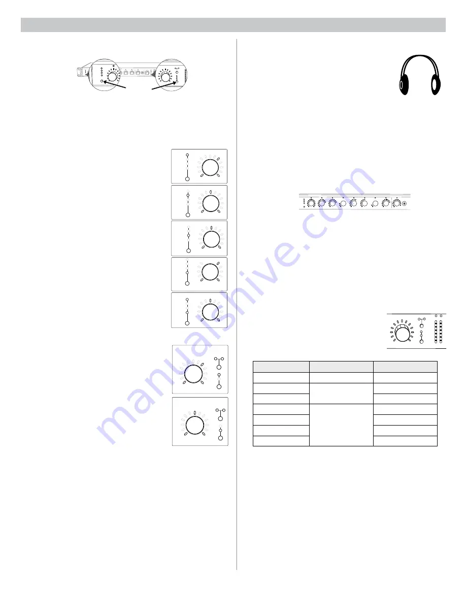
Operating the Mixer
Channel Gain (
gain
)
Adjust gain within a 128 dB range while displaying
the gain setting on the LED ring. Unity gain is at the
9th LED.
Low Cut (
low cut
)
Adjust the frequency of the low cut filter (6 dB/octave
from 25 to 320 Hz). Use to remove low-frequency
noise such as table vibrations or air-conditioning
rumble.
High Shelf (
hi shelf
)
Adjust the high shelf boost or cut (± 12 dB at 5
kHz). Use to add presence to muddy vocals, temper
sibilant vocals, or enhance the sound of off-axis
lavalier microphones.
Input Signal Meter (
ch. meter
)
LEDs display the input signal level in real-time.
Channel gain is adjustable in this mode, and will
momentarily display channel gain setting during
adjustments.
IntelliMix Gain Meter (
gain
and
ch. meter
)
LEDs display the IntelliMix attenuation applied
in realtime. Channel gain is adjustable in this
mode, displaying the setting on the LEDs during
adjustments.
Mix Outputs
The mix output knob operates in two modes to control
the mix output. Use the master function button to
select one of two modes.
Output Gain (
gain
)
Rotate to adjust the output gain of the selected mix.
The output signal level is displayed on the meters.
Limiter Threshold (
limiter
)
Rotate to adjust the limiter threshold of the mix (−2
to −50 dBFS). The limiter threshold level is displayed
on the meters.
Monitoring
Headphone Output
Use the front panel headphone jack for monitoring
audio. By default, the headphones monitor the mix pre-
fader/post-EQ (change to post-fader/post-limiter from
GUI > Preferences Tab
).
Solo to Headphones
A channel can be soloed to the headphone jack.
Solo Channel
: Press a channel knob to solo that channel to the
headphones. The other LED rings dim to highlight the soloed channel.
Exit Solo
: Press the soloed channel knob or press the
Master
knob to
return the mix to the headphones.
Input Meters
The front panel channel meters can be set to display real-time signal
information. Use the front panel mode selection button to scroll to the
desired mode:
Input Signal Level
The channel meter mode (
ch. meter
) displays real-time audio input signal
level for each channel.
IntelliMix Gain
The IntelliMix meter mode (
gain
and
ch. meter
illuminated) displays
IntelliMix gain operation in real-time across the channel LEDs. Channels
that gate open will display more gain than channels that are closed
(attenuated) in the mix.
AUX IN
L+R SUM
gain
low cut
hi shelf
meter
IntelliMix®
1
2
3
4
5
6
7
8
AUX IN
MASTER
lockout
power
ethernet
network audio
automix link
dual mixer
LIM
A
B
-9
-18
-24
-36
-48
-60
0
gain
limiter
L+R SUM
gain
low cut
hi shelf
meter
push to solo | hold to mute
1
2
3
4
5
6
7
8
A B
HEADPHONE
IntelliMix®
SCM820
gain
low cut
hi shelf
meter
push to solo | hold to mute
1
2
3
4
5
IntelliMix®
AUX IN
MASTER
LIM
A
-9
-18
-24
-36
-48
-60
0
gain
limiter
L+R SUM
A B
AUX IN
MASTER
lockout
power
ethernet
network audio
automix link
dual mixer
LIM
A
B
-9
-18
-24
-36
-48
-60
0
gain
limiter
L+R SUM
gain
low cut
hi shelf
meter
push to solo | hold to mute
1
2
3
4
5
6
7
8
A B
HEADPHONE
IntelliMix®
SCM820
For Channels 1-8
and Aux
For Mix
Outputs
Front Panel Modes
Audio Mute and Bypass
Mute Channel Input
Press and hold the input channel knob while in
gain
or
ch. meter
mode. The
channel status LED turns red.
Mute Mix Output
Press and hold the
MASTER
knob while in
gain
mode. The mix status LED
turns red.
Bypass Input EQ
Press and hold the input channel knob while in
low cut
or
hi shelf
mode. The
channel status LED turns amber.
Bypass Output Limiter
Press and hold the
MASTER
knob while in
limiter
mode. The mix status
LED turns amber.
Channel Inputs
The channel knobs operate in five modes for different types of input signal
adjustment and display. Use the front panel mode selection button to select
from the following modes.
Changing the Metering Type
Go to the Preferences tab of the GUI to change the following metering
options:
• Meter Type: Change the input and output meters from displaying VU +
Peak (default) to VU or Peak.
• IntelliMix Gain Metering: The Input tab of the GUI can display input
signal level (default) or IntelliMix gain metering in realtime.
Mode
Selector