4
lockout
line
A
A
B
B
manual
smooth
classic
extreme
custom
dual mixer
+0dB
mic
+30dB
mic
phm 48 VDC
CH
+46dB
reset
CHANNEL
INTELLIMIX
primary
secondary
00:0E:DD:AA:BB:CC
INPUTS 1-8
AUX IN
MIX OUTPUTS
MIX A
MIX B
L +R
SUM
DIRECT OUTPUTS 1-8
auto link
4
5
OUT
L R
mix a
mix b
AUX IN
+
7
+
ga
te
IN
mut
e
o
vr
d
gnd
+
direct out
8
+
ga
te
IN
mut
e
o
vr
d
gnd
+
direct out
6
+
ga
te
IN
mut
e
o
vr
d
gnd
+
direct out
+
ga
te
IN
mut
e
o
vr
d
gnd
+
direct out
+
ga
te
IN
mut
e
o
vr
d
gnd
+
direct out
3
+
ga
te
IN
mut
e
o
vr
d
gnd
+
direct out
2
+
ga
te
IN
mut
e
o
vr
d
gnd
+
direct out
1
+
ga
te
IN
mut
e
o
vr
d
gnd
+
direct out
lockout
line
A
A
B
B
manual
smooth
classic
extreme
custom
dual mixer
+0dB
mic
+30dB
mic
phm 48 VDC
CH
+46dB
reset
CHANNEL
INTELLIMIX
00:0E:DD:AA:BB:CC
auto link
primary
secondary
line
A
A
B
B
manual
smooth
classic
extreme
custom
dual mixer
+0dB
mic
+30dB
mic
phm 48 VDC
CH
+46dB
CHANNEL
INTELLIMIX
auto link
⑨ ⑫ ⑬
⑧⑩
⑪
⑯
⑰ ⑱
⑰ ⑱
⑰ ⑱
⑭ ⑮
①
②
①
②
③
④
⑦
⑥
⑤
③
⑭ ⑮
④
⑤
⑥
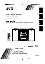
Rear Panel
① Power Switch
Turns the unit on or off.
② AC Power Jack
Supplies AC power to the mixer when plugged into a power source.
③ Mix A and Mix B Outputs
Active balanced outputs connect to amplifiers, DSP, mixer, or recording
device.
④ Auxiliary Input Jack
Unbalanced aux input sums left and right channels to mono. Front and
back panel aux inputs are summed to a mono signal and routed
without
automixing
to the mix outputs.
⑤ Channel Inputs 1–8
Active-balanced microphone- or line-level inputs.
Block Connectors
+
: Audio +
: Audio −
: Audio ground
gate
: Logic gate out
mute
: Logic mute in
ovrd
: Logic override in
gnd
: Logic ground
DB25 Connector
Pins
: Audio plus, audio negative and audio ground. See Specifications
for details.
⑥ Direct Outputs 1–8
Each channel has a dedicated, impedance-balanced direct output on
the back panel that can be selected from one of five stages in the signal
path. See Configuring the Inputs and Outputs for details on direct output
routing.
⑦ Chassis Ground Screw 1–8
Provides an optional connection for microphone shield wire to chassis
ground.
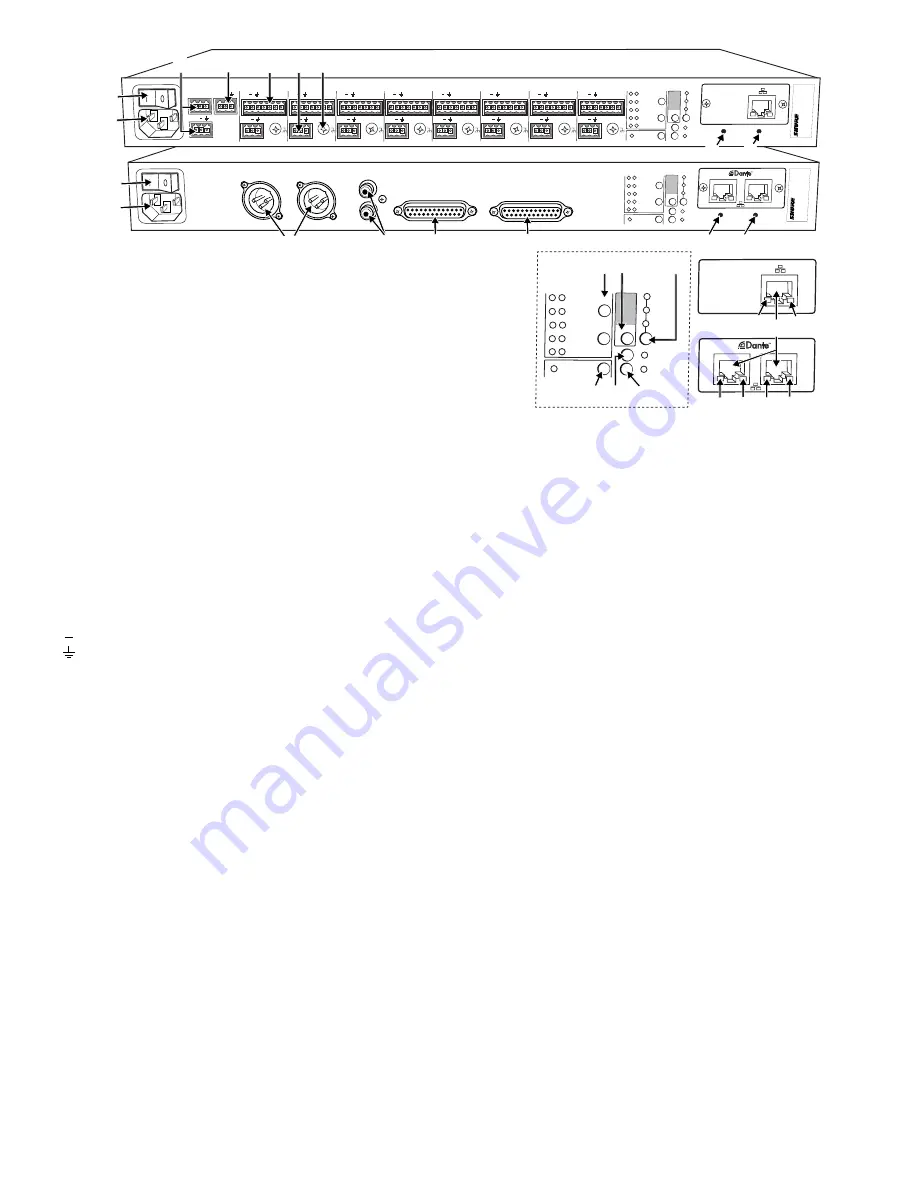
⑧ IntelliMix Select Buttons
Scrolls through IntelliMix presets for each mix output. When
dual mixer
is
off, the
A
button sets the mode for both Mix A and Mix B.
⑨ Dual Mixer Button
Sets the SCM820 as a dual mixer, indicated by the green LED.
⑩ Channel Select Button and Display
Press to select a single channel (1–8) or all channels (
A
) when changing
input gain or phantom power.
• When all channels are selected (
A
), Input Level and Phantom Power
LED indicators only illuminate if all channels have the same setting.
•
L
is displayed when the mixer is in lockout mode.
⑪ Input Gain Selection and LED Indicator
Sets the analog input gain level for the selected channel(s), illuminating
the green LED. All LEDs are off when the channel's audio source is set to
Network from the GUI.
⑫ Phantom Power Button and LED Indicator
Supplies 48 VDC phantom power to the selected channel(s), illuminating
the green LED. Phantom Power is disabled in the line (+0dB) gain setting.
⑬ Auto Link Button and LED Indicator
Enables networked SCM820-DAN mixers to automatically form a link
group. Link Groups enable a larger audio mix by incorporating inputs from
two or more mixers. See Link Groups for more details.
⑭ Lockout Button and LED Indicator
Hold for five seconds to disable front and back panel controls. The front
panel
lockout
LED illuminates red (flashing red during an adjustment
attempt) and the back panel channel display shows
L
.
⑮ Reset Button
Press and hold for five seconds to reboot the mixer with default system
settings restored.
⑯ Network Ports
RJ-45 jacks for network connection.
⑰ Network Status LED (Green)
Off
= no network link
On
= network link established
Flashing
= network link active
⑱ Network Speed LED (Amber)
SCM820:
Off = 10 Mbps
On = 100 Mbps
SCM820-DAN:
Off = 10/100 Mbps
On = 1 Gbps