background image


14 


Ordercode: 43740 

Helix M1000 Q4 Mobile 

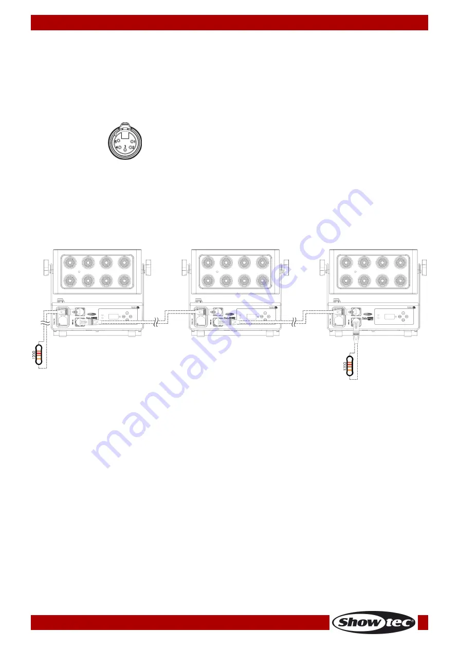
Multiple Helixes (Master / Slave Control) 
01)


Fasten the effect light onto firm trussing. Leave at least 0,5 meter on all sides for air circulation. 

02)


Always use a safety cable (ordercode 70140 / 70141). 

03)


Plug the end of the electric mains power cord into a proper electric power supply socket. 

04)


For the light output to be visible, press the power switch ON/OFF (08). The current from the built-in 
battery is responsible for the light output. The True1 pro power cable should be used only when 
charging the battery.
 

05)


Use a 5-pin XLR cable to connect the Helix.  


The pins: 


01)


Earth 

02)


Signal (-) 

03)


Signal (+) 

04)


N/C 

05)


N/C 


06)


Link the units as shown in Fig. 10. Connect a DMX signal cable from the first unit's DMX "out" socket to 
the second unit's "in" socket. Repeat this process to link the second and third units. Press the power 
switches ON/OF (08) on all slave devices, for the light output to be visible.
 You can use the same 
functions on the master device as described on pages 26–27. This means that you can set your 
desired operation mode on the master device and all slave devices will react the same as the 
master device. 

 
Multiple Helixes (Master/Slave Set Up) 


Fig. 10 


Summary of Contents for Helix M1000 Q4 Mobile

Page 1: ...Helix M1000 Q4 Mobile V1 Highlite International B V Vestastraat 2 6468 EX Kerkrade the Netherlands Ordercode 43740 MANUAL ENGLISH ...

Page 2: ...ontrol 15 Multiple Helixes Wireless DMX Control 16 Wireless DMX Connection 16 Wireless DMX Problems 16 Connect the Helix to the Wireless DMX Signal Transmitter 16 Disconnect the Helix from the Wireless DMX Signal Transmitter 16 Example 1 17 Example 2 18 Charging the built in battery 19 Fixture Linking 19 Data Cabling 20 Control Panel 21 DMX Control Mode 21 DMX Addressing 21 Menu Overview 22 Main M...

Page 3: ... 6 7 Calibration 30 6 8 Delayed Output 31 6 9 Factory 31 7 Information 31 DMX Channels 32 4 Channels 32 6 Channels 32 10 Channels 33 Maintenance 35 Troubleshooting 35 No Light 35 No Response to DMX 35 Product Specifications 37 Dimensions 38 ...

Page 4: ...Mobile Schuko to True1 pro power cable 1 5 m 1 x safety cable 1 x quick lock bracket User manual LED Expected Lifespan LEDs gradually decline in brightness over time HEAT is the dominant factor that leads to the acceleration of this decline Packaged in clusters LEDs exhibit higher operating temperatures than in ideal or singular optimum conditions For this reason when all color LEDs are used at th...

Page 5: ...ut close to flammable liquids or gases Always keep case closed while operating Always allow free air space of at least 50 cm around the unit for ventilation Always disconnect power from the mains when device is not used or before cleaning Only handle the power cord by the plug Never pull out the plug by tugging the power cord Make sure that the device is not exposed to extreme heat moisture or dus...

Page 6: ...r damages and the warranty becomes void Any other operation may lead to dangers like short circuit burns electric shock crash etc You endanger your own safety and the safety of others Rigging Please follow the European and national guidelines concerning rigging trussing and all other safety issues Do not attempt the installation yourself Always let the installation be carried out by an authorized ...

Page 7: ...e Helix M1000 Q4 Mobile can be placed on a flat stage floor by means of the included mounting bracket or be mounted to any kind of truss with a clamp and a quick lock bracket Improper installation can cause serious damage to people and property ...

Page 8: ...tion proper UPS packing or double boxing is always a safe method to use Note If you are given an RMA number please include the following information on a piece of paper inside the box 01 Your name 02 Your address 03 Your phone number 04 A brief description of the symptoms Claims The client has the obligation to check the delivered goods immediately upon delivery for any short comings and or visibl...

Page 9: ...Graphical display with 4 touch buttons Light source 8 x Prolight Opto RGBW 4 in 1 10 W LEDs Light output 2 m 8000 lx Refresh rate 12 kHz Dim curves 4 DMX modes 4 6 10 channels Dimmer 0 100 Strobe 0 20 Hz Beam angle 10 optional 20 40 15 x60 beamshapers Tilt Angle 0 180 Control modes Auto Built in programs Manual Master Slave DMX512 W DMX Power connectors True1 pro power connector IN OUT Data connec...

Page 10: ... V True1 pro power connector OUT 05 5 pin DMX connector OUT 06 5 pin DMX connector IN 07 OLED display control buttons Back Fig 02 08 Power switch ON OFF for battery operation Press this switch for the light output to be visible The current from the built in battery is responsible for the light output The True1 pro power cable should be used only when charging the battery ...

Page 11: ...connected properly Always disconnect from electric mains power supply before cleaning or servicing Damages caused by non observance are not subject to warranty Installing the Beamshapers 43745 43746 43747 01 In order to install the Beamshaper place it on the lens of the Helix The Beamshaper is equipped with multiple magnets which keep it firmly in position 02 For extra safety use a safety cable to...

Page 12: ...ws on both sides of the Barndoor to unlock the mechanism Fig 04 02 Place the Barndoor on the Helix to secure the Barndoor s screws in the Helix s mounting holes Fig 05 03 Release both locking screws to lock the Barndoor in position 04 For extra safety use a safety cable to connect the Barndoor to the Helix Fig 06 ...

Page 13: ...screws on both sides of the Tophat to unlock the mechanism Fig 07 02 Place the Tophat on the Helix to secure the Tophat s screws in the Helix s mounting holes Fig 08 03 Release both locking screws to lock the Tophat in position 04 For extra safety use a safety cable to connect the Tophat to the Helix Fig 09 ...

Page 14: ...e power switch ON OFF 08 The current from the built in battery is responsible for the light output The True1 pro power cable should be used only when charging the battery 05 When the Helix is not connected with a DMX cable it functions as a stand alone device 06 Please see pages 26 27 for more information about Auto and Built in programs One Helix Manual Mode 01 Fasten the effect light onto firm t...

Page 15: ... cable should be used only when charging the battery 05 Use a 5 pin XLR cable to connect the Helix The pins 01 Earth 02 Signal 03 Signal 04 N C 05 N C 06 Link the units as shown in Fig 10 Connect a DMX signal cable from the first unit s DMX out socket to the second unit s in socket Repeat this process to link the second and third units Press the power switches ON OF 08 on all slave devices for the...

Page 16: ...onnect a DMX signal cable from the first unit s DMX out socket to the second unit s in socket Repeat this process to link the second and third units 06 Supply electric power Plug electric mains power cords into each unit s True1 pro socket then plug the other end of the mains power cord into proper electric power supply sockets starting with the first unit Press the power switch ON OF buttons 08 o...

Page 17: ...signed to send wireless signals Therefore always connect the Helix devices to each other using a DMX cable Wireless DMX Problems 01 No signal from the W DMX transmitter The LED indicator will blink quickly 02 Proper connection with the W DMX transmitter but no DMX signal is present The LED indicator will blink slowly When the wireless DMX communication is unhindered and a DMX signal is present the...

Page 18: ...tures must always be connected via a DMX signal cable The Helix M1000 Q4 Mobile is only a W DMX receiver and never a W DMX transmitter When the Helix operates in DMX or Slave mode it can receive a wireless DMX signal CH1 512 and at the same time it can also send a DMX signal via its DMX output 05 through a DMX cable Fig 13 ...

Page 19: ... for wireless signal transmitters In order to pair the Helix with the wireless signal transmitter please check the manual of the wireless signal transmitter you use It is recommended to use the W DMX MicroBox F 1 G5 Transceiver 50175 by WIRELESS SOLUTION Disconnect from the Wireless DMX signal transmitter The Helix can be disconnected from the wireless DMX signal transmitter It is possible to deac...

Page 20: ...acity Please reduce the charge and discharge times to extend the battery lifetime After 300 times of charging and discharging you need to replace the battery Store in the upright position Fixture Linking You will need a serial data link to run light shows of one or more fixtures using a DMX 512 controller or to run synchronized shows on two or more fixtures set to a master slave operating mode The...

Page 21: ...150 1 5 m FL713 3 m FL716 6 m FL7110 10 m DAP Audio cable for the demanding user with exceptional audio qualities and connector made by Neutrik Ordercode FL7275 0 75 m FL72150 1 5 m FL723 3 m FL726 6 m FL7210 10 m DAP Audio 110 Ohm cable with digital signal transmission Ordercode FL0975 0 75 m FL09150 1 5 m FL093 3 m FL096 6 m FL0910 10 m FL0915 15 m FL0920 20 m DAP Audio data cable FL08 DMX AES E...

Page 22: ...x should be 1 10 11 011 the DMX address of the third Helix should be 11 10 21 021 etc Please be sure that you do not have any overlapping channels in order to control each Helix correctly If two or more Helixes are addressed similarly they will work similarly Controlling After having addressed all Helix fixtures you may now start operating these via your lighting controller Note After switching on...

Page 23: ...22 Ordercode 43740 Helix M1000 Q4 Mobile Menu Overview ...

Page 24: ...23 Ordercode 43740 Helix M1000 Q4 Mobile ...

Page 25: ...While in the main menu press the UP DOWN buttons to choose DMX 02 Press the SET button to enter the menu The display will show 03 Press the UP DOWN buttons to select one of the 4 submenus Address Channels Signal W DMX unlock 04 Press the SET button to open the desired submenu 1 1 Address With this menu you can set the desired DMX starting address 01 Press the UP DOWN buttons to set the desired DMX...

Page 26: ...rm your choice 1 3 Signal With this menu you can set the DMX signal type 01 Press the UP DOWN buttons to set the desired DMX signal type Choose one of the 2 options DMX Conventional DMX W DMX Wireless DMX 02 Press the SET button to confirm your choice 1 4 W DMX Unlock With this menu you can unlock the wireless DMX 01 Press the UP DOWN buttons to choose YES to unlock the wireless DMX or NO to retur...

Page 27: ...reate an infinite range of colors 0 255 3 Auto Mode With this menu you can set Auto mode 01 While in the main menu press the UP DOWN buttons to choose AUTO 02 Press the SET button to enter the menu The display will show 03 Press the UP DOWN buttons to choose YES to start the auto show or NO to return to the previous screen 04 Press the SET button to confirm your choice 4 Built in Programs With thi...

Page 28: ...s to choose one of the 2 options SPEED STROBE 03 Press the SET button to enter the desired menu 04 If you have chosen SPEED press the UP DOWN buttons to set the built in program s speed The adjustment range is between 1 100 from slow to fast Press the SET button to save your settings 05 If you have chosen STROBE press the UP DOWN buttons to set the strobe frequency The adjustment range is between ...

Page 29: ...T button to enter the menu The display will show 03 Press the UP DOWN buttons to choose one of the 9 submenus CURVES SELECT DIMMER SPEED DMX FAIL WORKING TIME DMX SYNC LOCK CALIBRATION DELAYED OUTPUT FACTORY 04 Press the SET button to enter the desired submenu 6 1 Curves Select 01 Press the UP DOWN buttons to choose one of the 4 dimming curves 02 Press the SET button to confirm your choice ...

Page 30: ...e light output HOLD The device will use last properly received DMX signal ensuring undisrupted performance MANUAL The device will switch to Manual mode PROGRAM The device will run the built in programs 02 Press the SET button to confirm your choice 6 4 Working Time With this menu you can set the working time of the Helix 01 Press the UP DOWN buttons to select one of the 16 options OFF Turns off th...

Page 31: ...the same action without any delays or OFF risk of random delays 02 Press the SET button to confirm your choice 6 6 Lock With this menu you can set the safety lock restricting access to the main menu 01 Press the UP DOWN buttons to select one of the 2 options ON When no button is pressed within 30 seconds the device s main menu will be locked In order to unlock it press and hold down the MODE and S...

Page 32: ... If you have chosen ON the device will wait for the determined amount of time and then it will activate its light output 6 9 Factory With this menu you can restore the default factory settings 01 Press the UP DOWN buttons to select YES or NO 02 Press the SET button to confirm your choice 7 Information With this menu you can view the device s current software version temperature total lifetime and ...

Page 33: ...er intensity from dark to brightest Channel 2 Strobe CH1 must be open CH3 6 must be open 0 10 Not functional 11 128 Random Strobe flash frequency from OFF to highest frequency 129 255 Strobe flash frequency from OFF to highest frequency Channel 3 Red CH1 must be open 0 255 Gradual adjustment Red from dark to brightest Channel 4 Green CH1 must be open 0 255 Gradual adjustment Green from dark to bri...

Page 34: ...eep Gold Amber 29 34 Millennium Gold 35 40 Gold Amber 41 46 Yellow 47 52 Chrome Yellow 53 58 Deep Amber 59 64 Spring Yellow 65 70 Lime Green 71 76 JAS Green 77 82 Fern Green 83 88 Moss Green 89 94 Primary Green 95 100 Dark Green 101 106 Green 107 112 Medium Blue Green 113 118 Light Blue 119 124 Lighter Blue 125 130 Steel Blue 131 136 CT Blue 137 142 Full CT Blue 143 148 State Blue 149 154 Double C...

Page 35: ...235 Section flow 3 236 245 Section flow 4 246 255 Section flow 5 Channel 5 Built in program speed CH8 must be set between 6 255 0 255 Gradual speed adjustment from slow to fast Channel 6 Color switch Color flow CH1 must be open 0 36 No functional 37 73 Dimmer Fast 74 110 Dimmer Slow 111 147 Linear curve 148 184 Square curve 185 221 Inv Square curve 222 255 S type curve Channel 7 Red CH1 must be op...

Page 36: ...rts of the device have to be tightly connected and must not be corroded 02 There may not be any deformations on housings fixations and installation spots 03 Mechanically moving parts like axles eyes and others may not show any traces of wearing 04 The electric power supply cables must not show any damages or material fatigue Troubleshooting No Light If the light effect does not operate properly re...

Page 37: ... link Bad data link connection Inspect connections and cables Correct poor connections Repair or replace damaged cables Data link not terminated with 120 Ohm termination plug Insert termination plug in output jack of the last fixture on the link Incorrect addressing of the fixtures Check address setting One of the fixtures is defective and disturbs data transmission on the link Bypass one fixture ...

Page 38: ... Tilt angle 0 180 Battery Lithium ion Battery voltage 18 5 V Battery storage 13 Ah Battery life time 8 h Full 15 h by software Charging cycle 6 h Rigging Quick locks for fast rigging and mounting Wireless DMX Wireless Solutions IP rating IP65 DMX control via standard DMX controller Onboard OLED Graphical display with 4 touch buttons Control modes Auto Built in programs Manual Master Slave DMX512 W...

Page 39: ...38 Ordercode 43740 Helix M1000 Q4 Mobile Dimensions ...

Page 40: ... 2019 Showtec ...

Reviews: