


65(147)
board.
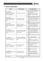
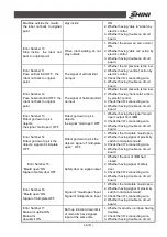
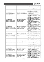
Error Number 18
Main arm forward limit ON
Main arm backward ON
Both forward limit and
backward limit of main arm
have signals input at the
same time
1. Whether the switch on main arm up
/down having troubles.
2. Check the I/O
’
s connecting wire.
3. Whether having trouble on circuit
board.
Error Number 19
Main arm up limit ON
Main arm downward ON
Both up limit and down limit
of sub arm have signals
input at the same time
1. Whether sub arm up /down having
troubles.
2. Check the I/O
’
s connecting wire.
3. Whether having trouble on circuit
board.
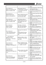
Error Number 20
Main arm forward limit ON
Main arm backward ON
Both forward limit and
backward limit of sub arm
have signals input at the
same time
1. Whether the switch on sub arm up
/down having troubles.
2. Check the I/O
’
s connecting wire.
3. Whether having trouble on circuit
board.
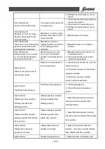
Error Number 21
Dais out limit ON
Dais in limit ON
Both dais out limit and
dais in limit having signal
input at the same time
1. Whether Dais out limit and Dais in
limit having troubles.
2. Check the I/O
’
s connecting wire.
3. Whether having trouble on circuit
board.
Error Number 22
Pose horizontal limit ON
Pose vertical limit ON
Both pose horizontal limit
and
pose vertical limit having
signal input at the same
time
1. Whether the switch of pose
horizontal limit and pose vertical
limit having troubles.
2. Check the I/O
’
s connecting wire.
3. Whether having trouble on circuit
board.
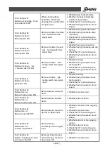
Error Number 23
Before arm down,
the signal of the
“
mould
open
”
OFF
Before arm down to pick,
the signal of the
“
mould
open
”
OFF
1. Whether having signal
“
mould
open
”
output
2. Check the I/O
’
s connecting wire.
3. Whether having trouble on circuit
board.
Error Number 24
Before arm down,
the signal of mild-plate OFF
Before robot down to pick
up the subjects the signal
of middle mode OFF
1. Whether the mid-plate mould open
2. Whether having signal of proximity
switch in mid-plate mould
3. Check the I/O
’
s connecting wire.
4. Whether having trouble on circuit
board.
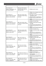
Error Number 25
Before arm down,
The signal of the safety door
OFF
Before arm down, the safety
door have no signals
1. Whether the safety door close.
2. Whether having the signals of
safety door.
3. Check the I/O
’
s connecting wire.
4. Whether having trouble on circuit
board.
Error Number 26
Before arm downing, the
pose vertical limit OFF
When choosing Pose
vertical , before arm
downing, Pose vertical limit
no signal input
1. Whether jig in vertical state.
2. Whether the vertical testing switch
having troubles.
3. Check the I/O 's connecting wire.
4. Whether having trouble on circuit
board.
Summary of Contents for ST1-1100-1800
Page 1: ...ST1 Single Axis Servo Driven Robot User Manual Date May 2016 Version V1 4 English ...
Page 2: ......
Page 46: ...46 147 Picture 2 3 X025 sensor Picture 2 4 X 025 lights up ...
Page 76: ...76 147 7 Assembly Diagram 7 1 Traverse Unit ST1 and ST1 T Picture 7 1 ...
Page 88: ...88 147 7 2 Vertical Unit ST1 Picture 7 2 ...
Page 93: ...93 147 7 3 Main arm unit ST1 Picture 7 3 ...
Page 98: ...98 147 7 4 Sub Arm unit ST1 Picture 7 4 ...
Page 101: ...101 147 7 5 Main Arm ST1 T Picture 7 5 ...
Page 104: ...104 147 7 6 Sub arm ST1 T Telescopic Arm Picture 7 6 ...
Page 107: ...107 147 7 7 Vertical ST1 T Telescopic Arm Picture 7 7 ...
Page 110: ...110 147 7 8 Traverse unit ST1 T Middle Telescopic Arm Picture 7 8 ...
Page 115: ...115 147 7 9 Main Arm ST1 T Middle Telescopic Arm Picture 7 9 ...
Page 120: ...120 147 7 10 Sub arm ST1 T Middle Telescopic Arm Picture 7 10 ...
Page 125: ...125 147 7 11 Crosswise Unit ST1 T Middle Telescopic Arm Picture 7 11 ...
Page 129: ...129 147 8 Electric Control Chart 8 1 The Power Input Wiring Diagram Picture 8 1 ...
Page 130: ...130 147 8 2 Main Control Panel and I O Wiring Diagram Picture 8 2 ...
Page 131: ...131 147 8 3 Panasonic Servo Motor Wiring Diagram 1 Picture 8 3 ...
Page 132: ...132 147 8 4 Panasonic Servo Motor Wiring Diagram and Spare Wiring Diagram M1 3 Picture 8 4 ...
Page 133: ...133 147 8 5 YASKAWA Servo Motor Wiring Diagram 1 Picture 8 5 ...
Page 134: ...134 147 8 6 YASKAWA Servo Motor Wiring Diagram and Spare Wiring Diagram M1 3 Picture 8 6 ...
Page 135: ...135 147 8 7 Z axis Wiring Diagram Picture 8 7 ...
Page 136: ...136 147 8 8 Main Arm Wiring Diagram 1 Picture 8 8 ...
Page 137: ...137 147 8 9 Main Arm Wiring Diagram 2 Picture 8 9 ...
Page 138: ...138 147 8 10 Sub Arm Wiring Diagram Picture 8 10 ...
Page 139: ...139 147 8 11 EM67 Signal Input Wiring Diagram Picture 8 11 ...
Page 140: ...140 147 8 12 EM67 Signal Output Wiring Diagram Picture 8 12 ...
Page 141: ...141 147 8 13 Main Control Board Component Layout Picture 8 13 ...
Page 142: ...142 147 8 14 I O U2 Board Component Layout 0 Picture 8 14 ...
Page 144: ...144 147 8 16 Main Arm U4 Layout Picture 8 16 ...
Page 145: ...145 147 8 17 Sub arm U5 Component Layout Picture 8 17 ...
Page 147: ...147 147 ...


