


37(147)
C7
C9
Reserved for future Euromap signal
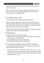
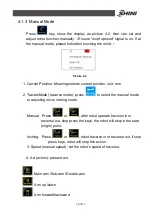
2.6.2 Euromap12 Interface
The interface consists of the plug connection between the injection molding
machine and the robot:
Picture 2-4
The robot-injection molding machine interface is designed according to
Euromap12, which state:
Unless otherwise noted, the signals are maintained during the described
function.
2.6.2.1 Injection Molding Machine Output Signals
Plug Contact NO.
Function
1
,
9
Emergency stop of machine
The emergency stop switch of the injection molding machine is used to
interrupt the emergence stop circuit of the robot.
2
Mold open
The switch contact (pin contact 16) is closed when mould opening position is
equal or more than required position. Inadvertent alteration to mould opening
stroke smaller than that required for the handing device to approach must be
impossible.
3
,
11
Safety system active
The switch contact is closed when safety devices (e.g. safety guard,
footboard safety, etc.) on the injection molding machine are operative so that
dangerous movements of the handing device/robot are possible. The signal is
active in any operation mode.
4
Ejector back
The switch contact is closed when the ejector has been retracted regardless
of the moving platen position. (See pin contact No.16) acknowledgement f or
Summary of Contents for ST1-1100-1800
Page 1: ...ST1 Single Axis Servo Driven Robot User Manual Date May 2016 Version V1 4 English ...
Page 2: ......
Page 46: ...46 147 Picture 2 3 X025 sensor Picture 2 4 X 025 lights up ...
Page 76: ...76 147 7 Assembly Diagram 7 1 Traverse Unit ST1 and ST1 T Picture 7 1 ...
Page 88: ...88 147 7 2 Vertical Unit ST1 Picture 7 2 ...
Page 93: ...93 147 7 3 Main arm unit ST1 Picture 7 3 ...
Page 98: ...98 147 7 4 Sub Arm unit ST1 Picture 7 4 ...
Page 101: ...101 147 7 5 Main Arm ST1 T Picture 7 5 ...
Page 104: ...104 147 7 6 Sub arm ST1 T Telescopic Arm Picture 7 6 ...
Page 107: ...107 147 7 7 Vertical ST1 T Telescopic Arm Picture 7 7 ...
Page 110: ...110 147 7 8 Traverse unit ST1 T Middle Telescopic Arm Picture 7 8 ...
Page 115: ...115 147 7 9 Main Arm ST1 T Middle Telescopic Arm Picture 7 9 ...
Page 120: ...120 147 7 10 Sub arm ST1 T Middle Telescopic Arm Picture 7 10 ...
Page 125: ...125 147 7 11 Crosswise Unit ST1 T Middle Telescopic Arm Picture 7 11 ...
Page 129: ...129 147 8 Electric Control Chart 8 1 The Power Input Wiring Diagram Picture 8 1 ...
Page 130: ...130 147 8 2 Main Control Panel and I O Wiring Diagram Picture 8 2 ...
Page 131: ...131 147 8 3 Panasonic Servo Motor Wiring Diagram 1 Picture 8 3 ...
Page 132: ...132 147 8 4 Panasonic Servo Motor Wiring Diagram and Spare Wiring Diagram M1 3 Picture 8 4 ...
Page 133: ...133 147 8 5 YASKAWA Servo Motor Wiring Diagram 1 Picture 8 5 ...
Page 134: ...134 147 8 6 YASKAWA Servo Motor Wiring Diagram and Spare Wiring Diagram M1 3 Picture 8 6 ...
Page 135: ...135 147 8 7 Z axis Wiring Diagram Picture 8 7 ...
Page 136: ...136 147 8 8 Main Arm Wiring Diagram 1 Picture 8 8 ...
Page 137: ...137 147 8 9 Main Arm Wiring Diagram 2 Picture 8 9 ...
Page 138: ...138 147 8 10 Sub Arm Wiring Diagram Picture 8 10 ...
Page 139: ...139 147 8 11 EM67 Signal Input Wiring Diagram Picture 8 11 ...
Page 140: ...140 147 8 12 EM67 Signal Output Wiring Diagram Picture 8 12 ...
Page 141: ...141 147 8 13 Main Control Board Component Layout Picture 8 13 ...
Page 142: ...142 147 8 14 I O U2 Board Component Layout 0 Picture 8 14 ...
Page 144: ...144 147 8 16 Main Arm U4 Layout Picture 8 16 ...
Page 145: ...145 147 8 17 Sub arm U5 Component Layout Picture 8 17 ...
Page 147: ...147 147 ...


