


31(147)
1) Release stop package
“
B
”
2) Run the X1-axis to the 0-position
3) Manually push cylinder piston rod to the fully extended state
4) Fix the stop package
“
B
”
Adjusting the 0-Position of X2-axis
:
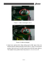
1) Run the X2 -axis to its 0-position
2) Release bracket
“
A
”
3) Manually push bracket
“
A
”
to ole-strut, in the compression state
4) Fix the stop package
“
A
”
Adjusting the End-Position of X2-Axis
(
the length of stroke
)
:
1) Release stop package
“
B
”
2) Run the X2-axis to its end- position
3) Manually push cylinder piston rod to the fully extended state
4) Fix the stop package
“
B
”
2.4.2 Adjusting the Y-
Position
Set the end-position of Y-axis by adjusting up-going shock absorber.
Adjusting the End-Position of Y-axis
:
1) Loosen shock absorber on the end position
2) Push the cylinder on Y-axis to its end position
3) Rotate the up-going shock absorber to the in the fully compression state
4) Fix the shock absorber
The withdrawal position can be set using the stop package
Adjusting the Withdrawal Position
1) Run the Y-axis to its end position
2) Seal off the compressed air
3) Loosen the Y-axis stop package
4) Manually push Y-axis to the desired position
5) Push stop package to ole-strut, in the compression state
6) Fix the Y-stop-package
Note: The down shock absorber completely compressed, the top position of
shock absorber shall not be lower than the origin of position sensor switch,
Summary of Contents for ST1-1100-1800
Page 1: ...ST1 Single Axis Servo Driven Robot User Manual Date May 2016 Version V1 4 English ...
Page 2: ......
Page 46: ...46 147 Picture 2 3 X025 sensor Picture 2 4 X 025 lights up ...
Page 76: ...76 147 7 Assembly Diagram 7 1 Traverse Unit ST1 and ST1 T Picture 7 1 ...
Page 88: ...88 147 7 2 Vertical Unit ST1 Picture 7 2 ...
Page 93: ...93 147 7 3 Main arm unit ST1 Picture 7 3 ...
Page 98: ...98 147 7 4 Sub Arm unit ST1 Picture 7 4 ...
Page 101: ...101 147 7 5 Main Arm ST1 T Picture 7 5 ...
Page 104: ...104 147 7 6 Sub arm ST1 T Telescopic Arm Picture 7 6 ...
Page 107: ...107 147 7 7 Vertical ST1 T Telescopic Arm Picture 7 7 ...
Page 110: ...110 147 7 8 Traverse unit ST1 T Middle Telescopic Arm Picture 7 8 ...
Page 115: ...115 147 7 9 Main Arm ST1 T Middle Telescopic Arm Picture 7 9 ...
Page 120: ...120 147 7 10 Sub arm ST1 T Middle Telescopic Arm Picture 7 10 ...
Page 125: ...125 147 7 11 Crosswise Unit ST1 T Middle Telescopic Arm Picture 7 11 ...
Page 129: ...129 147 8 Electric Control Chart 8 1 The Power Input Wiring Diagram Picture 8 1 ...
Page 130: ...130 147 8 2 Main Control Panel and I O Wiring Diagram Picture 8 2 ...
Page 131: ...131 147 8 3 Panasonic Servo Motor Wiring Diagram 1 Picture 8 3 ...
Page 132: ...132 147 8 4 Panasonic Servo Motor Wiring Diagram and Spare Wiring Diagram M1 3 Picture 8 4 ...
Page 133: ...133 147 8 5 YASKAWA Servo Motor Wiring Diagram 1 Picture 8 5 ...
Page 134: ...134 147 8 6 YASKAWA Servo Motor Wiring Diagram and Spare Wiring Diagram M1 3 Picture 8 6 ...
Page 135: ...135 147 8 7 Z axis Wiring Diagram Picture 8 7 ...
Page 136: ...136 147 8 8 Main Arm Wiring Diagram 1 Picture 8 8 ...
Page 137: ...137 147 8 9 Main Arm Wiring Diagram 2 Picture 8 9 ...
Page 138: ...138 147 8 10 Sub Arm Wiring Diagram Picture 8 10 ...
Page 139: ...139 147 8 11 EM67 Signal Input Wiring Diagram Picture 8 11 ...
Page 140: ...140 147 8 12 EM67 Signal Output Wiring Diagram Picture 8 12 ...
Page 141: ...141 147 8 13 Main Control Board Component Layout Picture 8 13 ...
Page 142: ...142 147 8 14 I O U2 Board Component Layout 0 Picture 8 14 ...
Page 144: ...144 147 8 16 Main Arm U4 Layout Picture 8 16 ...
Page 145: ...145 147 8 17 Sub arm U5 Component Layout Picture 8 17 ...
Page 147: ...147 147 ...


